


Revision A9 23
GRT Avionics Mini-X Installation, Setup & User Manual
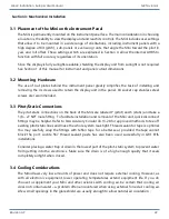
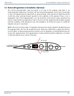
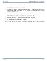
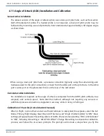
3.5 Remote Magnetometer Installation (Optional)
The remote magnetometer must be placed in an area of the airplane with little or no
electromagnetic interference. The cable is 20 feet long and designed to reach out to the wingtip
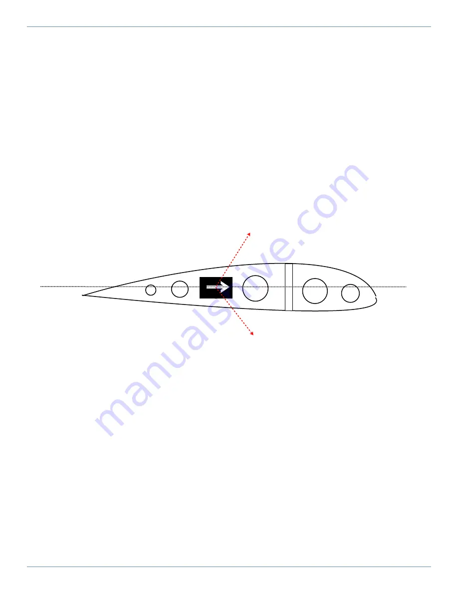
or tail. The magnetometer is marked with an arrow pointing in the direction of flight. Mount the
it with the arrow pointing forward, parallel to the centerline of the airplane. There is not a
designated “top” of the magnetometer, so it can be turned on its side for easier mounting. The
side of a wing tip rib is a simple place to put it. The arrow on the magnetometer should be parallel
with the centerline of the airplane for yaw. Pitch attitude is not critical as long as it is within 60
degrees nose up or nose down.
NOTE:
The most common cause of magnetic sensing error is simply magnetic disturbances near
the magnetometer. This can be caused by ferrous metal (any metal that a magnet will stick to),
control cables, or cable carrying electrical currents, such as navigation or landing lights, being too
close to the magnetometer. The magnetometer’s location will be tested for interference in Section
4, after the initial boot-up checks of the Mini.
Longitudinal Axis
60° up limit
60° down limit


