


Model T1243 (Mfd. Since 02/18)
-13-
4. Move mill table in and out to indicate across
full width of T1243 table.
5. If dial indicator reads evenly across T1243
table face, securely clamp it to milling machine
table.
6. If dial indicator does not read evenly, loosen
hold-down clamps and lightly tap T1243 to
adjust position. Repeat
Step 4 until indicator
reads evenly across full table width.
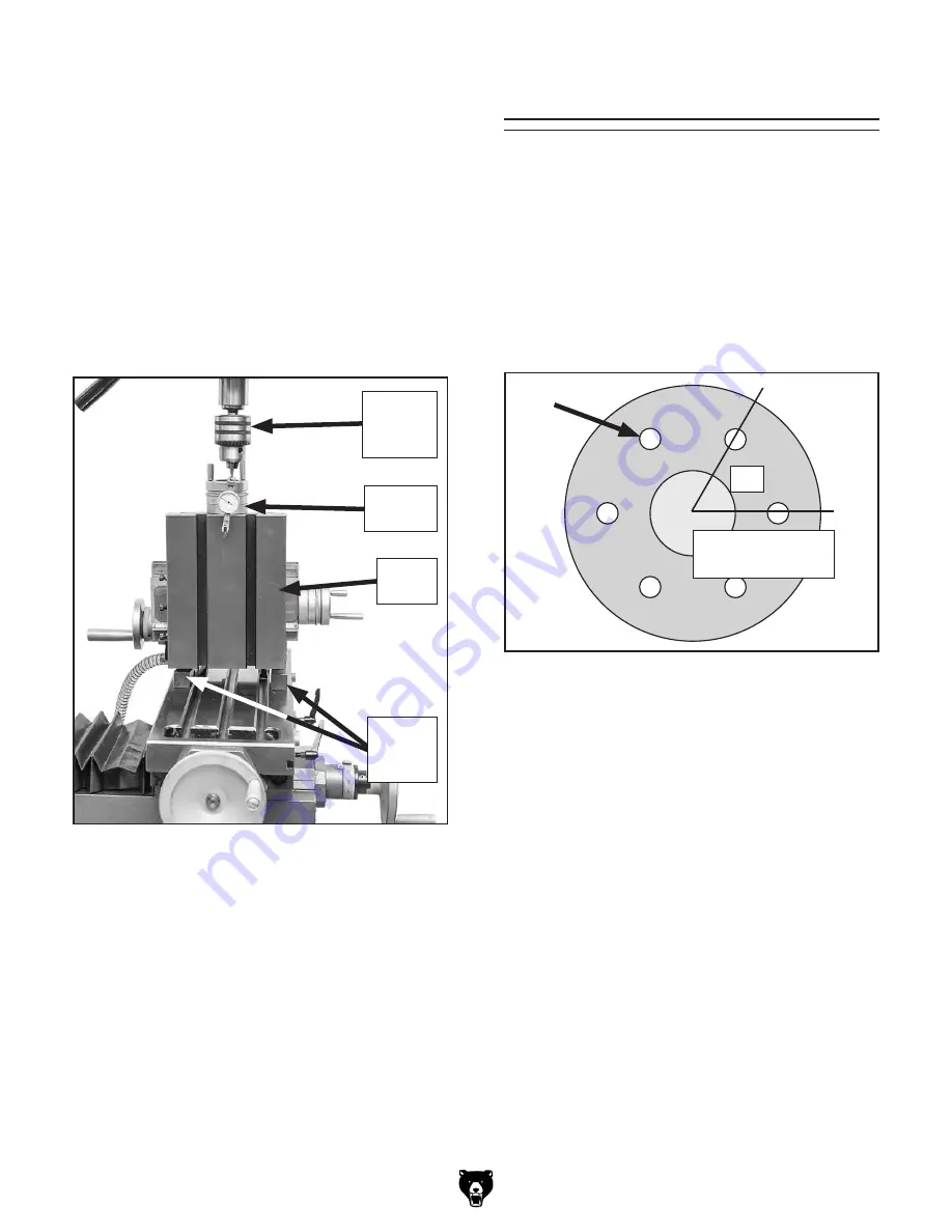
Angular Indexing
Basic Example:
You are making a flange and need to place six
holes 60° apart for the bolt pattern in
Figure 18.
Handwheel Rotations =
90
⁄
N
N = the desired division number (6).
90
/
6
= 15 full handwheel turns
15 turns = 60°
1. Rotate handwheel before making first hole to
take up any play in worm gear.
2. Make your first hole, then rotate handwheel
15 times.
Note: If you rotate handwheel too far, do not
back up to the number. You must back up
one revolution and dial back to the desired
number, then lock table in place to locate
the second hole. This procedure eliminates
errors due to backlash in worm gear.
Figure 18. Example of flange layout.
60°
Angular indexing is the process used to create
evenly spaced holes in a round workpiece. Always
ensure your rotary table is properly aligned on
the X-axis of the mill before beginning angular
indexing.
60°=15 Turns of
the Handwheel
To align T1243 with milling machine X-axis:
1. Place parallel step blocks on mill table.
2. Place T1243 vertically on step blocks so that
table sits beneath milling machine spindle,
as shown in
Figure 17. Mount T1243 to mill
table with T-bolts and hold-down clamps.
Finger-tighten fasteners.
3. Install dial indicator in milling machine spin-
dle, then use dial indicator to indicate one
side of face or back of a workpiece mounted
on T1243 table (see
Figure 17).
Figure 17. Using a dial indicator to align T1243
table with milling machine X-axis.
T1243
Table
Milling
Machine
Spindle
Dial
Indicator
Parallel
Step
Blocks