


-72-
Model G0899 (Mfd. Since 10/20)
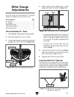
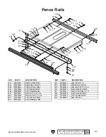
Figure 126. Fence components used to adjust
fence height and squareness to table.
Lock Nut
Fence Flange
Knob
(1 of 3)
Rear Rail
Foot
Top
Adjustment Screws
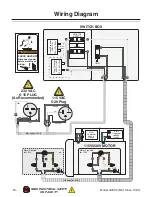
Figure 128. Example of aligning fence to miter
slot.
Fence
Face
Miter
Slots
Top View
Overlap
Side View (Bad)
Flush
Side View (Good)
A
B
The rear set screws control the position of the
fence in relation to the blade and the clamping
pressure of the fence. Before starting this pro-
cedure, make sure the blade is parallel with the
miter slot.
To adjust fence parallelism and clamping
pressure:
1. DISCONNECT MACHINE FROM POWER!
2. Lock fence, tap front side with your fist, and
check to see if it moved sideways over table.
— If fence did not move, proceed to
Step 5.
— If fence moved, remove it from table and
proceed to
Step 3.
3. Turn each rear set screw in
1
⁄
6th
of a turn (see
Figure 125 on Page 71). Glide pads on fence
flange should just touch fence tube.
4. Re-install fence and repeat Step 2.
5. Slide fence against right-hand edge of miter
slot and lock it in place, as shown in
Figure
128.
Parallelism & Clamping Pressure
6. Turn top adjustment screws and rear foot
screw so there is approximately
1
⁄
16
" clear-
ance between bottom of fence and table,
front-to-back and side-to-side, then tighten
lock nuts.
7. Place square on table and against face of
fence, as shown in
Figure 127, to check if
fence is square to table.
— If fence is square to table, proceed to
Parallelism & Clamping Pressure.
— If fence is not square to the table, proceed
to
Step 8.
Figure 127. Checking if fence is square to table.
90° Square
Fence
Table
8. Loosen top lock nuts and adjust top screws
(see
Figure 126) to make fence face 90° to
table, then tighten lock nuts.
4. Install fence onto table, then loosen fence
knobs (see
Figure 126), pull fence up from
center, and tighten each knob.
5. Loosen top lock nuts on fence flange and lock
nut on rear rail foot, shown in
Figure 126.
Содержание G0899
Страница 92: ......