Grizzly G0899 Скачать руководство пользователя страница 38

-36-

Model G0899 (Mfd. Since 10/20)

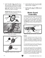
— If spreader/riving knife is not inside align-

ment  zone  and  not  parallel  with  blade, 
then  it  needs  to  be  adjusted.  Proceed  to 

Adjusting Alignment on Page 70.

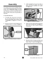
Figure 53. Spreader/riving knife alignment zone.

Alignment

Zone

Spreader or

Riving Knife

Blade

Straightedge

4.  While  lifting  up  on  one  side  of  blade  guard 

and  right  spreader  pawl,  place  straightedge 
against  blade  and  spreader,  making  sure 
straightedge does not touch a blade tooth.


When  properly  aligned,  spreader/riving 
knife  will  be  in  "Alignment  Zone,"  shown  in 

Figure 53, and will be parallel with blade.
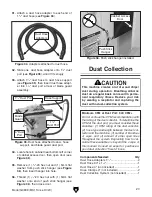
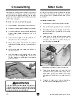
Anti-Kickback Pawls

The  anti-kickback  pawls  allow  the  workpiece 
to  travel  in  only  one  direction.  If  the  workpiece 
moves backwards, such as during a kickback, the 
pawls will dig into the workpiece to slow or stop it.

To  work  properly,  the  pawls  must  return  to  their 
resting  position  after  pivoting,  as  shown  in 

Figure 55, and they must NOT be engaged in the 
arresting hooks.

If the pawls fail to return to the resting position, the 
pivot area may need to be cleaned or the spring 
may have been dislodged or broken and will need 
to be fixed/replaced.

Figure 55. Pawls in resting position.

Pawl

Arresting Hooks

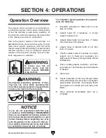
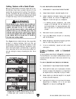
5 .  Connect dust collection hose to blade guard 

as shown in 

Figure 54. For more information, 

see 

Dust Collection on Page 27.

Figure 54. Dust port and dust collection hose 

installed on blade guard.

Dust Hose

Dust Port

Содержание G0899

Страница 1: ...s manufactured since 10 20 COPYRIGHT DECEMBER 2019 BY GRIZZLY INDUSTRIAL INC REVISED NOVEMBER 2020 MN WARNING NO PORTION OF THIS MANUAL MAY BE REPRODUCED IN ANY SHAPE OR FORM WITHOUT THE WRITTEN APPRO...

Страница 2: ...g grinding tool integrity and the usage of personal protective equipment The manufacturer will not be held liable for injury or property damage from negligence improper training machine modifications...

Страница 3: ...38 Ripping 39 Crosscutting 40 Miter Cuts 40 Blade Tilt Bevel Cuts 41 Dado Cutting 41 Rabbet Cutting 43 Resawing 45 SECTION 5 SHOP MADE SAFETY ACCESSORIES 50 Featherboards 50 Push Sticks 53 Push Blocks...

Страница 4: ...machine We made every effort to be exact with the instruc tions specifications drawings and photographs in this manual Sometimes we make mistakes but our policy of continuous improvement also means th...

Страница 5: ...n to instructions on reducing risk of kickback f Do not perform any operation freehand g Never reach around or over saw blade Identification Become familiar with the names and locations of the control...

Страница 6: ...andwheel D Blade Tilt Handwheel Adjusts angle of blade tilt from 90 45 E Blade Height Handwheel Adjusts blade height from 0 31 8 F Fence Lock Handle Locks fence when pushed down unlocks fence when pul...

Страница 7: ...details Kerf The resulting cut or gap in the workpiece after the saw blade passes through during a cutting operation Kickback An event in which the workpiece is propelled back towards the operator at...

Страница 8: ...2 lbs Length x Width x Height 30 x 25 x 42 in Must Ship Upright Yes Carton 2 Type Cardboard Box Content Fence Rails Weight 67 lbs Length x Width x Height 69 x 20 x 8 in Must Ship Upright No Electrical...

Страница 9: ...Diameter 10 500 FPM Table Information Floor to Table Height 34 1 4 in Table Size with Extension Wings Width 40 1 8 in Table Size with Extension Wings Depth 27 in Distance Front of Table to Center of B...

Страница 10: ...r Location Machine ID Label Sound Rating 87 dB Certified by a Nationally Recognized Testing Laboratory NRTL Yes Features Fully Enclosed Quick Release Blade Guard and Spreader Quick Release Riving Knif...

Страница 11: ...proof DANGEROUS ENVIRONMENTS Do not use machinery in areas that are wet cluttered or have poor lighting Operating machinery in these areas greatly increases the risk of accidents and injury MENTAL AL...

Страница 12: ...moving parts or flying debris Make sure they are properly installed undamaged and working correctly BEFORE operating machine FORCING MACHINERY Do not force machine It will do the job safer and better...

Страница 13: ...that have been dropped or damaged CUTTING CORRECT MATERIAL Cutting metal glass stone tile etc increases risk of operator injury due to kickback or flying particles Only cut natural and man made wood p...

Страница 14: ...cut Making a deep non through cut will greatly increase the chance of kickback Preventing Kickback Even if you know how to prevent kickback it may still happen Here are some ways to pro tect yourself...

Страница 15: ...on a power supply circuit that has a verified ground and meets the requirements listed below Refer to Voltage Conversion instructions for details Availability Before installing the machine consider t...

Страница 16: ...an extension cord only use it if absolutely necessary and only on a temporary basis Extension cords cause voltage drop which can damage electrical components and shorten motor life Voltage drop increa...

Страница 17: ...NEMA standard 6 15 plug wir ing is provided on Page 78 Figure 6 Motor prewired for 115V The voltage conversion MUST be performed by an electrician or qualified service personnel The voltage conversio...

Страница 18: ...ORE using machine Eye injury hazard Always wear safety glasses when using this machine Lifting heavy machinery or parts without proper assistance or equipment may result in strains back injuries crush...

Страница 19: ...s Head Screws 8 32 x 3 8 2 Hex Nuts 8 32 2 Y Hinge Pins 2 Z Push Stick Hangar 1 Hex Nuts 1 4 20 2 Flat Washers 5mm 2 NOTICE If you cannot find an item on this list care fully check around inside the m...

Страница 20: ...Table 2 AS Lock Washers 10mm Rear Rail Table 2 AT Hex Bolts M10 1 5 x 35 Rear Rail Wings 2 AU Flat Washers 10mm Rear Rail Wings 4 AV Lock Washers 10mm Rear Rail Wings 2 AW Hex Nuts M10 1 5 Rear Rail...

Страница 21: ...Model G0899 Mfd Since 10 20 19 Hardware Recognition Chart USE THIS CHART TO MATCH UP HARDWARE DURING THE INVENTORY AND ASSEMBLY PROCESS 5mm 5mm Flat Head Cap Screw...

Страница 22: ...following Disposable rags Cleaner degreaser WD 40 works well Safety glasses disposable gloves Plastic paint scraper optional Basic steps for removing rust preventative 1 Put on safety glasses 2 Coat t...

Страница 23: ...d space allocation Physical Environment The physical environment where the machine is operated is important for safe operation and lon gevity of machine components For best results operate this machin...

Страница 24: ...moothly first clean any parts that are cov ered or coated in heavy duty rust preventative if applicable Figure 18 Motor door installed Hinge Socket 5 Remove switch from inside saw cabinet and install...

Страница 25: ...re 21 Note After re installing wings remove all excess masking tape with a razor blade Figure 21 Masking tape location for adjusting the extension wing down 9 Attach front rail to table with 2 M10 1 5...

Страница 26: ...and 6mm lock washers as shown in Figure 24 Finger tighten fasteners 13 While standing at front of table pull rail tube toward you as far as possible then tighten fasteners installed in Step 12 This w...

Страница 27: ...d in Fence Adjustments on Page 71 so that it is parallel If miter slot is not parallel with blade you must follow procedures described in Miter Slot to Blade Parallelism on Page 67 22 Carefully slide...

Страница 28: ...gure 30 Rail tape aligned with scale pointer 28 Attach dust port to cabinet using 4 M5 8 x 12 button head cap screws and 4 6mm flat washers as shown in Figure 32 x 4 Figure 32 Dust port installed 29 P...

Страница 29: ...to cal culate these variables is beyond the scope of this manual Consult an expert or purchase a good dust collection how to book This machine creates a lot of wood chips dust during operation Breath...

Страница 30: ...malfunction or unexpect ed results that can lead to serious injury death or machine property damage Test Run Once assembly is complete test run the machine to ensure it is properly connected to power...

Страница 31: ...overview is to provide the nov ice machine operator with a basic understanding of how the machine is used during operation so the machine controls components discussed later in this manual are easier...

Страница 32: ...backer board creates extremely fine dust and may reduce the life of the motor bearings This machine is NOT designed to cut metal glass stone tile etc cutting these materials with a table saw greatly...

Страница 33: ...recommendations to ensure safe and efficient operation of your table saw Ripping Blade Features Best for cutting with the grain 20 40 teeth Flat top ground tooth profile Large gullets for large chip r...

Страница 34: ...an a standard blade Since the spreader riving knife included with this table saw is sized for standard blades thin kerf blades cannot be used on this saw unless they meet the Blade Requirements specif...

Страница 35: ...d on machine 4 While pressing arbor lock use included arbor wrench to loosen and remove arbor nut flange and blade see Figure 47 Arbor nut has right hand threads rotate counterclock wise to loosen Bef...

Страница 36: ...e see Page 38 Blade Guard Assembly The term blade guard refers to the assembly that consists of the clear polycarbonate shield and dust enclosure the spreader and the anti kickback pawls on each side...

Страница 37: ...ent if necessary Installing Blade Guard Spreader 3 Adjust flat head cap screws see Figure 52 to make sure table insert is flush with table use a straightedge as a guide Note The blade guard when prope...

Страница 38: ...ck Pawls The anti kickback pawls allow the workpiece to travel in only one direction If the workpiece moves backwards such as during a kickback the pawls will dig into the workpiece to slow or stop it...

Страница 39: ...or other specialized cuts Because the blade guard is provided to decrease your risk of injury it should not be used if it gets in the way of making a safe cut Use good judgment Disabling Pawls You mi...

Страница 40: ...fe The riving knife is installed in a similar manner to the blade guard and spreader Refer to Blade Guard Assembly on Page 34 for installation instructions To ensure that riving knife works safely it...

Страница 41: ...OWER 4 Ensure that blade guard spreader is installed 5 Loosen fence knobs see Figure 59 remove rip fence then re install in vertical position for normal cutting operations or in horizontal position fo...

Страница 42: ...igure 61 Typical crosscutting operation Crosscutting Miter Cuts A miter is an angled crosscut Miters are usually cut in the same manner as crosscuts using the miter gauge and a predetermined mark on t...

Страница 43: ...ng pulled into the blade if kickback occurs DO NOT use the riving knife if you install a dado blade smaller than 8 in diameter Otherwise the riving knife height will exceed the blade height and the wo...

Страница 44: ...ado length of a workpiece If dadoing across workpiece use miter gauge and carefully line up desired cut with dado blade To reduce kickback DO NOT use fence in combination with miter gauge 4 Reconnect...

Страница 45: ...ing operation on other side of dado as shown in Figure 67 8 Make additional cuts see Figure 68 in cen ter of dado to clear out necessary material Dado is complete when channel is complete ly cleared o...

Страница 46: ...s to reduce risk of kickback Cutting Rabbets with a Standard Blade A ripping blade is typically the best blade to use for cutting rabbets when using a standard blade because it removes sawdust very ef...

Страница 47: ...machine for resawing and resawing with one is fairly easy and safe A table saw is not intended for resawing and resawing with one is difficult and dangerous due to the increased risk of kickback from...

Страница 48: ...upport for the workpiece This minimizes the probability of it binding against the blade and causing kickback Tools Needed Qty Table Saw 1 Jointer and Planer Recommended Clamps 2 Minimum Drill 1 Drill...

Страница 49: ...n auxiliary fence and remove auxiliary fence board from fence tube 5 Using 7 32 drill bit drill mounting holes in auxiliary fence board Countersink holes 1 16 deep so head of flat head cap screws sits...

Страница 50: ...edure Stand to the side of the blade and wear safety glasses and a full face shield to prevent injury when resawing 4 Attach auxiliary fence and set it to desired width Note When determining correct w...

Страница 51: ...age 48 Leaving a 1 8 connec tion will reduce risk of kickback 8 Plug in table saw turn it ON and use a push stick or push block to feed workpiece through blade using a slow and steady feed rate Note W...

Страница 52: ...design Most featherboards are 10 28 long and 3 6 wide Make sure the wood grain runs paral lel with the length of the featherboard so the fingers you will create in Step 3 will bend without breaking 2...

Страница 53: ...Side View Wing Nut Miter Bar Featherboard Flat Head Screw Flat Washer Figure 82 Assembling miter slot featherboard components Note The routed slot countersink hole and flat head screw are essential f...

Страница 54: ...ounting Featherboards w Clamps 4 Secure featherboard to table with a clamp 5 Check featherboard by pushing it with your thumb to ensure it is secure If featherboard moves tighten clamp more 6 Optional...

Страница 55: ...k Push Stick Prohibition Zone Store Push Stick Here for Easy Access Supporting A second push stick can be used to keep the workpiece firmly against the fence while cutting When using a push stick in t...

Страница 56: ...Using a Push Block A push block can be used in place of or in addi tion to a push stick for feeding workpieces into the blade Due to their design push blocks allow the operator to apply firm downward...

Страница 57: ...row rip auxiliary fence and push block system shown in this section is an example of a specialty jig that can be made to increase the safety of very narrow rip cuts 2 Pre drill and countersink eight p...

Страница 58: ...Cutting Width Blade Auxilliary Fence Figure 94 Adjusting ripping distance between blade and auxiliary fence Auxilliary Fence Blade Workpiece Push Stick for Side Support Blade Path Push Block Figure 95...

Страница 59: ...ckback when crosscutting Crosscut Sled One of the best accessories for improving the safety and ease of using a table saw is simply plac ing a large table outfeed table behind the saw to catch the wor...

Страница 60: ...cut miter any depth Cuts all sized grooves 1 4 through 29 32 increments order online at www grizzly com or call 1 800 523 4777 Figure 100 T20779 Forrest Woodworker II Forrest Woodworker II 10 Blades T...

Страница 61: ...10V 220V 14A 7A Figure 103 Point of use dust collectors Model G0710 Model G1163P order online at www grizzly com or call 1 800 523 4777 Figure 104 T28922 Bear Crawl Mobile Base T28922 Bear Crawl Cub M...

Страница 62: ...977 The Missing Shop Manual Table Saw guide book Figure 105 Assortment of basic eye protection Basic Eye Protection T20501 Face Shield Crown Protector 4 T20502 Face Shield Crown Protector 7 T20503 Fac...

Страница 63: ...must be strictly followed Ongoing To minimize your risk of injury and maintain proper machine operation shut down the machine imme diately if you ever observe any of the items below and fix the proble...

Страница 64: ...ew location Clean away any built up grime and debris from the worm gear bull gear and leadscrew see Figures 110 111 with a wire brush rags and mineral spir its Allow the components to dry then apply a...

Страница 65: ...r at fault 1 Decrease feed rate cutting speed 2 Use correct sharp blade Page 31 3 Only cut wood replace crooked workpiece ensure moisture is below 20 4 Clean motor let cool and reduce workload Reset b...

Страница 66: ...reader not correctly aligned with blade 1 Replace blade Page 33 2 Use correct sharp blade Page 31 3 Adjust fence parallel with blade Page 72 4 Adjust miter slot parallel with blade Page 67 5 Adjust ri...

Страница 67: ...ow shown in Figure 113 points to 0 mark on scale Adjust position by loosening button head screw moving indicator with your fingers then tightening screw Figure 112 Checking blade at 90 Table 90 Square...

Страница 68: ...o next step 4 Tilt blade to 30 so there is room for stop collar to move 6 Place a 45 square against blade as shown in Figure 115 then adjust blade until it is exactly 45 to table 7 Without turning bla...

Страница 69: ...able square to measure distance from miter slot to a car bide tip on blade as shown in Figure 117 Make sure that face of adjustable square is even along miter slot The saw blade is sharp Use extra car...

Страница 70: ...th metal shim stock Continue to Step 9 9 Loosen 4 table mounting bolts from Step 6 Mounting Bolts Figure 119 Location of table mounting bolts table omitted for clarity 7 Repeat Steps 2 6 until blade a...

Страница 71: ...came apart Spreader or Riving Knife Alignment Checking Alignment The blade guard spreader and riving knife must be aligned with the blade when installed If the spreader riving knife is not aligned wi...

Страница 72: ...ap screws and wing nut on adjustment block then adjust top or bot tom set screws or side control set screws see Figure 124 to move block in need ed direction Note Set screws are accessible through cla...

Страница 73: ...lock to secure spreader riving knife adjustment Fence Adjustments There are four main adjustments for the fence height off the table squareness parallelism with the miter slot and clamping pressure Th...

Страница 74: ...igure 125 on Page 71 Glide pads on fence flange should just touch fence tube 4 Re install fence and repeat Step 2 5 Slide fence against right hand edge of miter slot and lock it in place as shown in F...

Страница 75: ...the chance of kickback by alleviating binding that may occur between blade and fence The trade off is slightly less accurate cuts To offset fence 1 DISCONNECT MACHINE FROM POWER 2 With a felt tip pen...

Страница 76: ...f workpiece Table Dado Insert Adjustment The table dado insert must sit perfectly flush with the table to provide a smooth continuous surface for the workpiece to slide over The insert is held in plac...

Страница 77: ...are touches miter body and body of blade not the teeth evenly at same time then it is square to blade and 90 stop is set correctly No further adjustments are necessary 5 Loosen lock nut on 90 set scre...

Страница 78: ...it will need to be tensioned If the belt is cracked frayed or shows other signs of excessive wear it will need to be replaced Replacing Belt 1 DISCONNECT MACHINE FROM POWER 2 Raise blade completely t...

Страница 79: ...t at the time of printing but may not match your machine If you find this to be the case use the wiring diagram inside the motor junction box CAPACITORS INVERTERS Some capacitors and power inverters s...

Страница 80: ...30V WARNING SHOCK HAZARD Disconnect power before working on wiring Motor Prewired for 115V GND Run Capacitor 30uF d 350VAC Neutral Hot Ground 115 VAC 5 20 Plug Ground Hot Hot 6 15 PLUG As Recommended...

Страница 81: ...D ELECTRICAL SAFETY ON PAGE 77 Electrical Components Figure 138 Motor junction box Motor Junction Box Figure 137 Motor capacitors Start Capacitor Run Capacitor Figure 139 Switch box wiring and compone...

Страница 82: ...LT SCALE 7 P0899007 TABLE INSERT MAGNET 28 P0899028 HINGE PIN 8V2 P0899008V2 MAIN TABLE V2 10 20 30 P0899030 STRAIN RELIEF TYPE 3 M16 1 5 9 P0899009 MOTOR ACCESS DOOR 31 P0899031 TABLE INSERT DADO 10...

Страница 83: ...33 109 107 108 109 108 135 108 109 135 108 135 134 184 110 111 136 161 186 186 112 137 162 187 187 206 206 128 138 163 188 188 114 139 139 189 115V2 140 164 190 116 141 166 191 117 142 167 167 192 118...

Страница 84: ...4 KEY 6 X 6 X 20 177 P0899177 TILT LEADSCREW BASE 115 P0899115 SET SCREW M6 1 X 10 178 P0899178 ROLL PIN 4 X 16 115V2 P0899115V2 SET SCREW M6 1 X 6 V2 10 20 179 P0899179 TILT LEADSCREW 116 P0899116 MO...

Страница 85: ...6 20 233 P0899233 STRAIN RELIEF TYPE 3 PG11 222V2 P0899222V2 PADDLE SWITCH UV03 006 V2 06 20 235 P0899235 POWER CORD 14G 3W 72 5 20P 223V2 P0899223V2 SWITCH BOX AP 9501B 205 JP950B V2 06 20 236 P08992...

Страница 86: ...24 P0899324 GUARD RIGHT 306 P0899306 GUARD LEFT 325 P0899325 TAP SCREW M3 X 10 307 P0899307 TAP SCREW M3 5 X 16 326 P0899326 RIVING KNIFE 308 P0899308 SPRING CLAMP 331 P0899331 HOSE SUPPORT ARM 309 P0...

Страница 87: ...899409 SET SCREW 10 24 X 1 4 401 P0899401 MITER HANDLE 5 16 18 X 1 410 P0899410 STOP LINK 402 P0899402 FLAT WASHER 5 16 411 P0899411 POINTER 403 P0899403 MITER GAUGE BODY 412 P0899412 SCALE 404 P08994...

Страница 88: ...V2 10 20 502 P0899502 KNURLED NUT M12 1 75 513 P0899513 PHLP HD SCR 10 24 X 3 8 503 P0899503 SET SCREW M12 1 75 X 20 NYLON TIPPED 514 P0899514 FLAT WASHER 10 504 P0899504 SET SCREW 3 8 16 X 5 16 515...

Страница 89: ...ON 602 P0899602 FENCE GUIDE TUBE 611 P0899611 HEX NUT M10 1 5 603 P0899603 FENCE RAIL FRONT 612 P0899612 FENCE RAIL REAR 604 P0899604 FENCE SCALE LABEL 613 P0899613 HEX BOLT M10 1 5 X 25 605 P0899605...

Страница 90: ...er cord into a grounded outlet 5 Always use blade guard spreader for all through cuts and use riving knife for all non through cuts If a certain cut cannot be made with either device some other safegu...

Страница 91: ...rty or for incidental contingent special or consequential damages arising from the use of our products The manufacturers reserve the right to change specifications at any time because they constantly...

Страница 92: ......

Отзывы: