


Model G0817 (Mfd. Since 05/16)
-69-
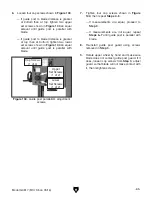
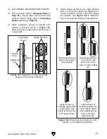
To adjust lower wheel shaft position:
1. DISCONNECT MACHINE FROM POWER!
2. Loosen jam nuts on lower wheel adjustment
hub (see
Figure 111).
Top Tilt
Side
Tilt
Bottom Tilt
Side
Tilt
Adjustment
Hub
Figure 111. Lower wheel adjustment controls.
3. Loosen one tilt adjustment set screw, then
tighten opposing set screw approximately an
equal amount.
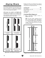
4. Check wheels with coplanarity gauge, and
repeat
Step 3 as needed until lower wheel is
parallel and coplanar with upper wheel.
5. Tighten jam nuts to lock tilt adjustment set
screws in position.
6. Perform previous Checking Wheel
Alignment procedure, beginning on Page
66, and adjust wheels as necessary to make
them parallel and coplanar.
7. When wheels are parallel and coplanar,
remove blade, re-install table, and then re-
install blade.
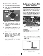
Calibrating Table Tilt
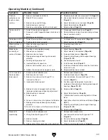
Scale Pointer
The table tilt scale pointer (see
Figure 112) was
calibrated at the factory. However, after prolonged
use the pointer may shift, requiring adjustment.
Note: The table tilt scale functions as a basic
guide only. For high-precision cuts, use a protrac-
tor or bevel gauge to set the angle of table tilt.
Figure 112. Location of table tilt scale and
pointer.
Pointer
Table Tilt
Scale
Tools Needed
Qty
Machinist's Square ............................................ 1
Phillips Screwdriver #2 ...................................... 1
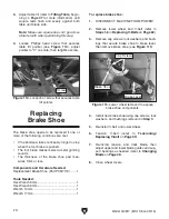
To calibrate table tilt scale pointer:
1. DISCONNECT MACHINE FROM POWER!
2. Place one edge of square on table and other
edge of square against blade side, as shown
in
Figure 113.
Figure 113. Adjusting table perpendicular to
blade (side to side).
Содержание G0817
Страница 88: ......