


-60-
Model G0812 (Mfd. Since 2/16)
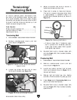
Figure 97. Using 60° square to check 60° left
angle stop.
— If square fits snugly against outer fixed jaw
and blade, no further steps are necessary
.
— If square does not fit snugly against outer
fixed jaw and blade, loosen jam nut shown
in
Figure 94 on Page 59. Thread stop
bolt inward or outward as necessary, until
square fits snugly against fixed jaw base
while base contacts stop bolt.
8. Tighten jam nut without turning stop bolt.
1. Repeat Steps 1–3 from Setting 45° Right
Angle Stop on Page 59.
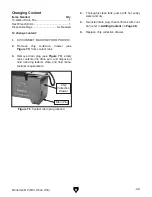
2. Rotate swivel lock handle toward base, then
rotate headstock clockwise until base con-
tacts 60° left stop bolt (see
Figure 96).
Setting 60° Left Angle Stop
3. Slide vise to right position and secure it. Refer
to
Changing Vise Position on Page 34.
4. Connect machine to power and lower head-
stock all the way until it stops moving.
Figure 96. 60° left stop bolt and jam nut location.
5. DISCONNECT MACHINE FROM POWER
and place 60° square between outer fixed
jaw and blade, as shown in
Figure 97. The
square should fit snugly against outer fixed
jaw and blade.
— If square fits snugly against outer fixed jaw
and blade, no further steps are necessary
.
— If square does not fit snugly against outer
fixed jaw and blade, loosen jam nut shown
in
Figure 96. Thread stop bolt inward or
outward as necessary until square fits
snugly against outer fixed jaw and blade
while base contacts stop bolt.
6. Tighten jam nut without turning stop bolt, then
tighten swivel lock handle to secure head-
stock.
60° Left Stop Bolt
Jam Nut
Blade
60°
Square
Outer Fixed Jaw
Содержание G0812
Страница 84: ......


