


Model G0812 (Mfd. Since 2/16)
-35-
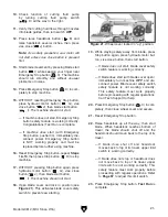
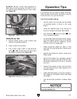
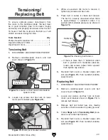
Figure 45. Quick-release latch location.
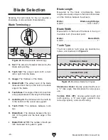
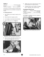
Using Movable Vise
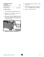
1. Loosen lock bolt shown in Figure 47 on
movable vise so jaw can match angle of
workpiece and fixed jaw.
2. Tighten movable vise against workpiece,
then tighten lock bolt.
Figure 47. Movable vise positioned for angled
workpiece.
Fixed Vise
1. DISCONNECT MACHINE FROM POWER!
2. Rotate vise handwheel (see Figure 45) coun-
terclockwise
1
⁄
2
-turn to relieve any pressure
on vise jaw.
3. Flip quick-release latch (see Figure 45) up to
disengage it from vise leadscrew.
Using Vise
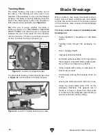
Figure 46. Example of workholding options by
material shape.
NOT
RECOMMENDED
RECOMMENDED
Note: Figure 46 shows correct methods of
holding different workpiece shapes.
4. Pull or push jaw in desired direction, as
required to accommodate workpiece.
5. Insert workpiece between jaws and engage
latch with leadscrew when vise is close to
workpiece. Use handwheel to move vise jaw
until it just contacts workpiece. If necessary,
use a stand to support long workpieces to
prevent tipping.
6. Reconnect machine to power.
7. Press hydraulic motor button (
B
A
C
D
E
F
G
H
I
J
K
L
).
8. Use vise close button (
STAND BY
START
<< I
OFF
1
2
3
4
5
6
7
8
9
0
HIGH
LOW
A
E
M
H
B
C
F
I
J
K
L
G
D
STOP
) to clamp
workpiece. Between cuts, use vise open but-
ton (
STAND BY
START
<< I
OFF
1
2
3
4
5
6
7
8
9
0
HIGH
LOW
A
E
M
H
B
C
F
I
J
K
L
G
D
STOP
) to release and reposition/reload a
new workpiece.
Note: As a safety precaution, the vise close
button (
STAND BY
START
<< I
OFF
1
2
3
4
5
6
7
8
9
0
HIGH
LOW
A
E
M
H
B
C
F
I
J
K
L
G
D
STOP
) must be pressed and saw head-
stock must be raised before saw motor and
blade will start.
Quick-
Release
Latch
Handwheel
Lock Bolt
Movable Vise
Содержание G0812
Страница 84: ......


