


-48-
Model G0812 (Mfd. Since 2/16)
The coolant system consists of a fluid tank, pump,
and hose with valves. The pump pulls fluid from
the tank and sends it to the valves, which control
the flow of coolant. As the fluid leaves the work
area, it drains through the cabinet, where the
swarf and metal chips are screened out, and back
into the tank.
Coolant System
Service
BIOLOGICAL & POISON
HAZARD!
Use correct personal
protection equipment
when handling coolant.
Follow federal, state,
and fluid manufacturer
requirements for proper
disposal.
Hazards
As coolant ages and gets used, dangerous
microbes can proliferate and create a biological
hazard. The risk of exposure to this hazard can
be greatly reduced by replacing the old fluid on a
monthly basis, or as indicated by the fluid manu-
facturer.
When working with the coolant, minimize expo-
sure to your skin, eyes, and lungs by wearing
the proper PPE (Personal Protective Equipment),
such as long-sleeve waterproof gloves, protective
clothing, splash-resistant safety goggles, and a
NIOSH-approved respirator.
Although most swarf from machining operations is
screened out of the coolant before it returns to the
tank, small particles will accumulate in the bottom
of the tank in the form of sludge. To prevent this
sludge from being pulled into the pump and dam-
aging it, the pump’s intake is positioned above the
bottom of the tank. This works well when the tank
is regularly cleaned; however, if excess sludge is
allowed to accumulate, the pump will inevitably
begin sucking it up.
Adding Coolant
Items Needed
Qty
Safety Wear ....................................See
Hazards
New Coolant ...................................... 7.5 Gallons
Disposable Shop Rags ...................... As Needed
To add coolant:
1. DISCONNECT MACHINE FROM POWER!
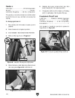
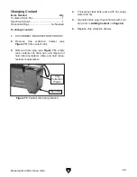
2. Remove chip collection drawer shown in
Figure 77.
3. Fill reservoir with coolant until it is at maxi-
mum fill line shown in
Figure 78.
Figure 77. Removing chip collection drawer.
4. Replace chip collection drawer.
Figure 78. Approximate maximum fill line on
filter screen.
Filter
Screen
Maximum
Fill Line
Содержание G0812
Страница 84: ......


