28
Defi nition of terms
Control functions, transmitter controls, function inputs, control channels, mixers, switches,
control switches, fi xed switches
Defi nition of terms
To make it easier for you to understand the
mx
-24s
manual, we present at this stage two pages of defi ni-
tions of terms which crop up again and again in the
remainder of the text, together with a basic fl ow chart
of the course of the signal from the transmitter con-
trol to the point where it is broadcast from the trans-
mitter aerial.
Control function
The term “control function” can be thought of as the
signal which is generated in order to control a par-
ticular function – initially independent of the course
of the signal in the transmitter. In the case of fi xed-
wing model aircraft, throttle, rudder and aileron repre-
sent control functions, whereas collective pitch, roll-
axis and pitch-axis are typical of those used to con-
trol model helicopters. The signal of a control func-
tion may be assigned directly to a control channel, or
to several control channels via mixers. A typical ex-
ample of the latter is a pair of separate aileron ser-
vos, or two roll-axis or pitch-axis servos in a model
helicopter. In particular, the control function includes
the infl uence of the travel of the mechanical transmit-
ter control on the corresponding servo. This can be
expanded or compressed by means of software; it is
also possible to modify the characteristics of the tra-
vel from linear at one end of the scale to extreme ex-
ponential at the other.
Transmitter control (CTRL)
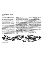
The term “transmitter control” refers to the mechani-
cal elements on the transmitter which are operated
directly by the pilot. Their movements in turn produce
corresponding movements in the servos, speed con-
trollers etc. at the receiver end. Transmitter controls
include the following:
• The
two
dual-axis stick
units for the control func-
tions 1 to 4; these four functions can be interchan-
ged in any way you like through software, e. g.
throttle left or right, without having to re-connect
the servos. The dual-axis stick function for thrott-
le or airbrake control is often known as the C1
(Channel 1) control.
• The two proportional controls
located on the sides of the case,
which are always referred to as
controls number 9 (right-hand
“rotary slider”) and 10 (left-hand
“rotary slider”) at various points
in the program.
• The two transmitter controls termed CONT-
ROL 5 and 6. On the
mx
-24s these have a
dual function:
a) If these two transmitter controls are not assi-
gned to any of the inputs in the »
Control ad-
just
« menu (see pages 78 and 80), they can
be used as INCrement / DECrement buttons for
adjusting values in the “+” (INC) and “-” (DEC)
directions, as an alternative to the ROTARY
control.
b) If they are assigned as transmitter controls in
the »
Control adjust
« menu, they change the
position of the associated servo by a 1% incre-
ment (relative to the currently set servo travel –
see the »
Servo adjustment
« menu) every time
they are pressed. The posi-
tions are superimposed on
the basic screen display im-
mediately the buttons are
pressed, or when you press
the rotary control. This is
ideal, for example, for set-
ting the camber-changing
fl aps to different positions in individual fl ight
phases. If they are held pressed in for a longer
time, the rate of change alters automatically –
made audible by a faster sequence of beeps.
You will also hear an audible signal when the
buttons reach the centre position.
Note:
The position of these two transmitter controls
is
always
stored separately for each fl ight pha-
se, provided that they have been assigned to
one of the inputs 5 … 12 in the »
Control ad-
just
« menu.
• However, the servos can also be swit-
ched between three different fi xed posi-
tions (forward - centre - back) by means
of the three-position switches termed
CONTROL 7 and 8. They can also be switched
between two positions (forward - back) using any
of the remaining switches (SW = abbreviation for
switch), e. g. from the one servo end-point to the
other. The individual positions which a servo takes
up at each switch position can be set individually
(see the »
Control adjust
« menu, pages 78 and
80, and the »
Servo adjustment
« menu, page 74).
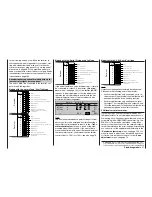
The transmitter control or switch which operates each
one of the servos 5 … max. 12 is freely programmab-
le, without restriction.
Important note:
In the default state of the transmitter software all
these inputs are set to “free”, i. e. they are not as-
signed to any functions as standard.
The numbers printed on the transmitter are intended
exclusively to help you keep track of the program-
ming procedure. Only in the Helicopter menu is the
right-hand side-mounted proportional control (CON-
TROL 9) already assigned to the “Throttle limit func-
tion”; see page 82. In the Helicopter menu, inputs 6,
7 and 12 are also assigned to “Throttle”, “Gyro” and
“Throttle limit” respectively, since helicopter-specifi c
functions are controlled using these inputs.
Physically and terminologically each transmitter cont-
rol terminates where it reaches the …
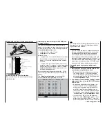
Function input
This is an imaginary point in the signal path, and
must not be considered the same as the point on the
circuit board where the transmitter control is connec-
ted. In fact, the line “Stick mode” of the menu »
Model
type
« and the menu »
Control adjust
« infl uence the
sequence “down-stream” of these connections, i. e. it
PCM20
ner
h C65
0 0
Stop
Flight
dame
Содержание mx-24s
Страница 1: ...1...
Страница 19: ...19 For your notes...
Страница 35: ...35 For your notes...
Страница 41: ...41 41 For your notes...
Страница 57: ...57 For your notes...
Страница 63: ...63 63 For your notes...
Страница 69: ...69 69 For your notes...
Страница 85: ...85 85 For your notes...
Страница 99: ...99 For your notes...
Страница 143: ...143 For your notes...
Страница 191: ...191 For your notes...
Страница 212: ...212 212 For your notes...
Страница 213: ...213 213 For your notes...
Страница 214: ...214 For your notes...
Страница 216: ...216...


