174
Using fl ight phases
Within any model memory you can program up to
eight different fl ight phases (stages of fl ight), each in-
corporating settings which can be entirely different
from those in the others.
Each fl ight phase can be called up by means of a
switch or combination of switches. Flight phases re-
present the simplest and most convenient method of
switching between different model settings in fl ight,
and they are usually programmed for different stages
of a typical fl ight, such as normal, thermal, speed,
distance etc.. However, fl ight phase programming can
also be used as a straightforward method of trying
out minor modifi cations to the control system – such
as different mixer ratios – while the model is in the air.
This makes it much quicker to fi nd the optimum set-
tings for a particular model.
However, before you start with the actual program-
ming, we recommend that you consider whether the
digital trims for aileron, elevator and rudder should be
“global” in effect – i. e. should be set to the same va-
lues in all fl ight phases – or should be “phase-speci-
fi c”, i. e. variable separately in each fl ight phase.
If you decide on, say, phase-specifi c elevator trim,
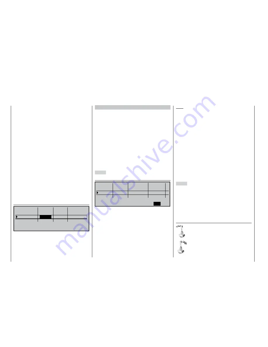
then move to the menu …
»Stick mode« (page 76)
0.0s 0.0s
0.0s 0.0s
0.0s 0.0s
SYM ASY
SEL
global
global
global
4
4
4
4
0.0s 0.0s
SEL
Phase
– time +
Channel 1
Aileron
Elevator
Rudder
Tr.step
Trim
… and alter the default “global” setting accordingly.
You may also like to exploit this opportunity to set the
number of trim increments in the “Trim increment” co-
lumn.
Example 1 …
… following up the earlier programming example:
an electric glider with two aileron servos.
The electric power system is controlled independent-
ly of the C1 stick, using one of the two side- mounted
proportional controls CONTROL 9 or 10, or one of
the two three-position switches CONTROL 7 or 8. The
speed controller is accordingly connected to receiver
output 9 as described in Examples 1 and 2 on page
166, on which this expanded programming procedure
is based. That is why we selected “none” in the “Motor
on C1” line of the »
Model type
« menu. This setting
has various ramifi cations, including the suppression
of the “Motor” column in the »
Phase settings
« menu,
and the unrestricted availability of the “Brake settings”
sub-menu in the »
Wing mixers
« menu.
Step 1
»Phase settings« (page 100)
Phase 1
Phase 2
1.0s
Phase 3
3.0s
Phase 4
SEL
Normal
2.0s
Thermal
0.0s
SEL
-
Speed
+
+
SEL
Name
Fl.ph.Tim
Sw. time
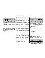
The fi rst step is to assign names to one or more fl ight
phases, which should describe the various stages
of fl ight. The name is important, as it helps you dif-
ferentiate between the individual phases when you
are programming and operating the model. The name
is always displayed on the screen in all the menus
which are variable separately for each fl ight phase.
However, the phase names have no signifi cance in
terms of programming.
The method of selecting the appropriate line and
name, and of setting up the transition time – by tur-
ning and pressing the rotary control – should now be
really familiar to you.
Note:
The names you assign to the various phases are of
no signifi cance in programming terms – with the ex-
ception of Phase 1, which should always be assigned
the name “normal”, as it is always active even if you
disable the fl ight phases.
For general model fl ying three fl ight phases are usu-
ally quite suffi cient:
• «Thermal» for launch and “staying up”,
• «normal» for normal fl ying conditions, and
• «Speed» for fl ying in “top gear”.
In the “Switch time” column you can defi ne the period
over which the transition from one phase
into
(!) ano-
ther fl ight phase occurs; this provides a smooth shift
between the different servo settings, and can prevent
a possibly damaging lurch when you switch between
different control surface settings under unfavourable
circumstances. An asterisk (
) in the “Status” column
indicates the fl ight phase which is currently active.
Step 2
You must assign a switch or switches so that you can
actually move between the different fl ight phases. The
ideal unit for switching a maximum of three fl ight pha-
ses is one of the two three-position switches (SW 5 +
6 or SW 9 + 10).
One fl ight phase is then assigned to each of the two
switch end-points A … F,
starting from the centre
point
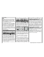
. The switches are assigned in the menu ...
»Phase assignment« (page 104)
First select the switch symbol below “C”,
press the rotary control briefl y and move the
switch to one end-point, then return it to the
centre position.
Now select the switch symbol below “D”,
give a brief press on the rotary control, and
move the switch to the opposite end-point.
174
Programming examples: Fixed-wing model
Содержание mx-24s
Страница 1: ...1...
Страница 19: ...19 For your notes...
Страница 35: ...35 For your notes...
Страница 41: ...41 41 For your notes...
Страница 57: ...57 For your notes...
Страница 63: ...63 63 For your notes...
Страница 69: ...69 69 For your notes...
Страница 85: ...85 85 For your notes...
Страница 99: ...99 For your notes...
Страница 143: ...143 For your notes...
Страница 191: ...191 For your notes...
Страница 212: ...212 212 For your notes...
Страница 213: ...213 213 For your notes...
Страница 214: ...214 For your notes...
Страница 216: ...216...


