108
108
Program description:
Timers
FL. phase timers
Selecting and setting
Timer 1
Timer 2
Timer 3
0:00
Lap time/Tim tab
Timer
Alarm
SEL
SEL
SEL
0s
0:00
0s
0:00
0s
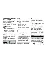
In the »
Phase assignment
« menu (see page 104)
we have already explained how one of these timers,
together with the “lap counter” or “Time1” or “Time2”,
is assigned to a fl ight phase. The characteristics of
these timers were also described in the same sec-
tion. The additional timer selected for a specifi c fl ight
phase is then included in the basic display above the
GRAUPNER/JR
logo or the name of the fl ight phase.
In this menu you can program “Clk 1 … 3” as stop-
watches, i. e. count-up timers, or as timers or alarm ti-
mers, i. e. count-down timers, and assign any switch
you like to the timer – as with the other timer variants.
The fl ight phase timers “Clk 1 … 3” and “Time1” and
“Time2” only operate in the fl ight phase to which they
are assigned. In the basic display they are also super-
imposed accordingly. In other fl ight phases they are
stopped (and suppressed), and the assigned start /
stop switch has no effect.
In contrast, the lap counter, once started, continues
running even if you switch fl ight phases (see below),
although it can be stopped from any fl ight phase by
pressing the
ESC
button.
Clk 1, 2 und 3
These timers are started and stopped by means of
a switch, control switch or logical switch. To set one
up, use the rotary control to select the switch symbol
on the right, then set the desired switch after a brief
press on the rotary control. Once again, assigning
a control switch offers you the opportunity to opera-
te the timer using a stick or other proportional trans-
mitter control. The switching point along the travel of
the transmitter control is determined in the »
Control
switches
« menu (see page 94).
Please note that the timer switches are also active in
programming mode.
Switching between “count-up” and “count-down”
mode
Stopwatch mode (count-up timer)
In this mode the timer starts at the initial value “0:00”
(min:sec) when you operate the assigned switch. If it
reaches the maximum time of 999 min. and 59 sec., it
will re-start at 0:00.
“Timer” (count-down timer)
If you activate the appropriate
SEL
fi elds below “Ti-
mer” using the rotary control in the left-hand highligh-
ted fi eld, and enter a time in minutes (maximum 180
minutes), and / or in the right-hand fi eld a time in se-
conds (maximum 59 seconds), then the timers run
backwards (“Timer” function) starting from this initi-
al value when you operate the assigned switch. When
the pre-set time has elapsed, the timer does not stop;
instead it continues running so that you can read off
the over-run, i. e. the time elapsed after zero.
Pressing
CLEAR
resets the input values in the cur-
rently active fi eld to zero.
Count-down timers
are identifi ed in the basic display
by a fl ashing colon (:) between the minutes and the
seconds fi elds.
“Alarm” timer
In the “Alarm” column you can defi ne a time within the
range 5 to 90 seconds in 5-second increments. At the
set time before zero you will hear an audible signal,
eliminating the need for the pilot constantly to check
the screen. The sequence of beeps is stated on the
previous page.
(Pressing
CLEAR
= 0 sec.)
Note:
If you alter the function of a timer, the new mode only
becomes active when you stop the timer and press
CLEAR
to reset it.
Like the two standard timers above it, this third ti-
mer is reset to the starting value of “0:00” or the Timer
start value when you press the
CLEAR
button, simul-
taneously in all fl ight phases, even if it has
not been
stopped
separately in the other fl ight phases.
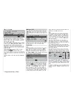
Typical display:
S o a r m a s t e r
#05
H-J.Sandbrunner
9.5V
2:30h C62
0
0
0
0
Stop watch
Flight tim
Clk 1
«Normal
»
1 35
1 35
12 23
:
:
:
0:50h SPCM20
In this case “Clk 1” was assigned to the “normal” fl ight
phase in the »
Phase assignment
« menu (see page
104).
Lap time / time tables
Only one switch has to be set in the “Lap time / time
tables” line. All the other softkey functions are sup-
pressed. We suggest that you select the momentary
switch SW 8 at this point: every time you press it, the
lap count is incremented, and at the same time the
time elapsed during this lap is automatically stopped
and recorded. The momentary switch simultaneously
starts the stopwatch for the next lap. The screen dis-
plays lap times up to max. 59.9 seconds in 1/10 se-
cond increments; above this in min:sec.
“Time1” and “Time2” operate in the same manner; for
more details please read the section describing the
»
Phase settings
« menu point.
At the end of the fl ight, press the
ESC
button at the
basic display in order to stop the timer and read out
the data.
Содержание mx-24s
Страница 1: ...1...
Страница 19: ...19 For your notes...
Страница 35: ...35 For your notes...
Страница 41: ...41 41 For your notes...
Страница 57: ...57 For your notes...
Страница 63: ...63 63 For your notes...
Страница 69: ...69 69 For your notes...
Страница 85: ...85 85 For your notes...
Страница 99: ...99 For your notes...
Страница 143: ...143 For your notes...
Страница 191: ...191 For your notes...
Страница 212: ...212 212 For your notes...
Страница 213: ...213 213 For your notes...
Страница 214: ...214 For your notes...
Страница 216: ...216...


