126
Program description:
Mixers
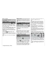
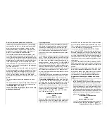
trol arc, all you need to do is to read off this optimised
value and transfer it to the reference point at control
centre.
Channel 1
tail rotor
0%
0%
0%
m
OU
T
P
U
T
--
+
1
10
0
1
»Normal «
Channel 1
Input
Curve
off
Point
Output
Tail rot.
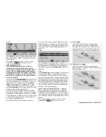
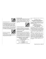
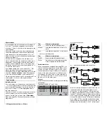
The purpose of this mixer is to provide static torque
compensation. The fi rst step is to ensure that the di-
rection of main rotor rotation has been entered cor-
rectly in the »
Helicopter type
« menu, page 72.
This mixer should be set up in such a way that the he-
licopter does not rotate around the vertical (yaw) axis
(i. e. does not deviate from the hover heading) during
a long vertical climb or descent, due to the change in
torque of the main rotor relative to the hover. At the
hover the yaw trim should be set using the digital tail
rotor trim lever only. For a reliable torque compensa-
tion setting it is essential that the collective pitch and
throttle curves have been set up correctly, i. e. that
main rotor speed remains constant over the full adjust-
ment range of collective pitch.
This third eight-point curve applies only to the control
curve of the tail rotor servo when the throttle / collec-
tive pitch stick is moved, whereas the “Channel 1 cur-
ve” (see page 92) infl uences all servos which are af-
fected by the throttle / collective pitch stick. Note that
the output signal of the “Channel 1 curve” also acts
as input signal for the tail rotor curve which is pro-
grammed at this point: the vertical line in the diagram,
which moves in parallel with the throttle / collective
pitch stick, follows the actual Channel 1 curve as set
in the »
Channel 1 curve
« menu.
As standard, the software includes a three-point tail
rotor curve with a linear mixer ratio of 30%. Using the
method described above, you can modify the mixer
by placing additional reference points on the curve,
and thereby set asymmetrical mixer ratios above and
below the hover point.
In the auto-rotation fl ight phase this mixer is auto-
matically switched off.
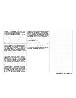
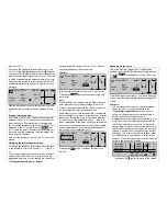
Note regarding the marker button:
If you have set the marker button in the »
Base setup
model
« menu (see page 66), a dotted vertical line
will appear in this graph when you operate the assig-
ned switch. This line indicates the position of the C1
stick the last time the switch was operated:
-30%
-30%
m
OU
T
P
U
T
--
+
1
10
0
?
»Normal «
Channel 1
Input
Curve
off
Point
Output
Tail rot.
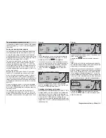
Move the C1 stick (solid line) to the marker line in or-
der to be able to read off and transfer the input and
output values, or to optimise this mixer by placing a
further reference point at this location.
Tail rotor
throttle
The normal purpose of the tail rotor is to compensa-
te for the effect of main rotor torque on the fuselage,
but it is also the primary method of controlling the he-
licopter around the vertical (yaw) axis. However, if you
increase tail rotor thrust by giving a yaw command,
motor power must also be increased to avoid a fall-off
in system rotational speed.
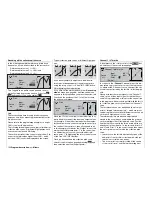
In this menu you set the extent to which the thrott-
le follows the tail rotor. The throttle only follows the
tail rotor on one side, i. e. to the side where tail ro-
tor thrust is increased, and the adjustment range is
therefore 0 to +100%. The direction of mixing varies
according to the direction of rotation of the main rotor
(left or right), and this must fi rst be set correctly in the
»
Helicopter type
« menu. For left-hand rotation sys-
tems, e. g.
HEIM/GRAUPNER
helicopters, the throttle
follows the tail rotor when the tail rotor stick is moved
to the left; with right-hand rotation systems: when the
stick is moved to the right.
In the auto-rotation fl ight phase this mixer is auto-
matically switched off.
Set-up notes:
To set the mixer value accurately you should fi rst fl y
several high-speed pirouettes in the direction of main
rotor rotation (i. e. with a HEIM system machine, pi-
rouette to the left). Alternatively, hover the helicop-
ter in a cross-wind heading on a fairly breezy day, hol-
ding in the required large tail rotor defl ection. The mi-
xer value should now be adjusted until the rotational
speed does not fall off in this situation. For a HEIM
system machine this value needs to be around 30%.
Roll
throttle and pitch-axis
throttle
Increasing collective pitch requires a corresponding
adjustment to the throttle setting, and the same ap-
plies if a major cyclic command is given i. e. if the
swashplate is tilted in any direction. In the
mx
-24s
program you can adjust the degree of throttle follo-
wing for roll-axis and pitch-axis separately.
These mixers offer particular advantages in aero-
batic fl ying, e. g. when fl ying a roll: collective pitch va-
lues are only moderate, and the throttle therefore
only about half-open, but the roll requires major cyc-
lic commands, and these require a much higher po-
wer input.
The mixer values can be varied within the range 0 to
+100%; the program automatically sets the correct di-
rection of mixing.
In the auto-rotation fl ight phase this mixer is auto-
matically switched off.
Содержание mx-24s
Страница 1: ...1...
Страница 19: ...19 For your notes...
Страница 35: ...35 For your notes...
Страница 41: ...41 41 For your notes...
Страница 57: ...57 For your notes...
Страница 63: ...63 63 For your notes...
Страница 69: ...69 69 For your notes...
Страница 85: ...85 85 For your notes...
Страница 99: ...99 For your notes...
Страница 143: ...143 For your notes...
Страница 191: ...191 For your notes...
Страница 212: ...212 212 For your notes...
Страница 213: ...213 213 For your notes...
Страница 214: ...214 For your notes...
Страница 216: ...216...


