141
Program description:
Mixers
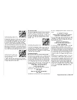
page of the screen display. Select
STO
using the
rotary control, then press the rotary control briefl y
… the offset value now jumps to +100% or -100%,
depending on the switch position you have selec-
ted.
Move
to
ASY
using the rotary control, operate the
selected switch to the mixer ON position, and en-
ter the required mixer input after a brief press on
the rotary control.
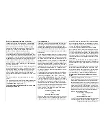
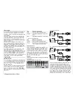
2. The airborne glowplug energizer of a power mo-
del is connected to receiver output 8. The pilot wi-
shes to be able to switch the unit on and off by ra-
dio, but also to switch it on and off automatically at
a particular position of the C1 stick in order to im-
prove the motor’s idling characteristics:
The fi rst step is to defi ne a logical switch, in our
example “L1”, by combining a switch of your
choice with a control switch, e. g. “G1”, which is al-
ready pre-defi ned on the C1 stick, using an
AND
link. (The control switch is assigned by activating
the switch assignment, then moving the C1 stick
back towards you from its centre position beyond
the switching point.) For more information on this
please refer to the »
Logical switches
« menu on
page 97.
Leave both the stick and the selected switch in the
“ON” position: this means that “L1” is also closed
due to the
AND
link:
L1
L2
L2
L3
L4
SEL
L1
L3
L4
7
G1
L O G I C A L S W I T C H E S
AND
AND
AND
AND
Now comes the second step: defi ne a switch
channel mixer “S” to “8” (for example), and assign
the previously defi ned – and still closed – “logical
switch” to this mixer as the switch; in our example
this is “L1”:
SEL
8
S
=>
L1
on
SEL
SEL
SEL
??
??
??
??
??
??
- - - -
- - - -
- - - -
LinearMIX 5
LinearMIX
LinearMIX
LinearMIX
6
7
8
from
to
Adjust
type
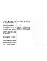
Now move to the second page of the screen dis-
play and set a
SYM
metrical mixer value in such
a way that the glowplug energizer is reliably swit-
ched “on”, and switched “off” when you move the
stick forward past the switching point or operate
the assigned switch.
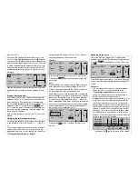
3. The fi nal example applies to model helicopters:
In the Helicopter program you wish to assign one
of the (still unused) INC / DEC transmitter but-
tons, e. g. CONTROL 5, to the collective pitch trim
function. Start by assigning this transmitter cont-
rol to, say, input 8 in the »
Transmitter control ad-
just
« menu, and then defi ne a free mixer 8
1
with a symmetrical mixer ratio of – typically – 25%.
Due to the internal coupling, this transmitter con-
trol then acts equally on all of the model’s collec-
tive pitch servos without affecting the throttle ser-
vo. However, you should also disengage the assi-
gned transmitter control from control channel 8 in
the »
MIX only channel
« menu, to ensure that any
servo connected to receiver output 8 (in our case)
can no longer be operated by this transmitter cont-
rol; see also page 43.
Note:
Of course, you could also use the left-hand side-
mounted proportional control 10, which is unused
by default, for the purposes of trimming. Howe-
ver, in contrast to the digital INC / DEC buttons
this does not store the settings separately for each
fl ight phase; see also page 28.
Содержание mx-24s
Страница 1: ...1...
Страница 19: ...19 For your notes...
Страница 35: ...35 For your notes...
Страница 41: ...41 41 For your notes...
Страница 57: ...57 For your notes...
Страница 63: ...63 63 For your notes...
Страница 69: ...69 69 For your notes...
Страница 85: ...85 85 For your notes...
Страница 99: ...99 For your notes...
Страница 143: ...143 For your notes...
Страница 191: ...191 For your notes...
Страница 212: ...212 212 For your notes...
Страница 213: ...213 213 For your notes...
Страница 214: ...214 For your notes...
Страница 216: ...216...

