106
Timers (general)
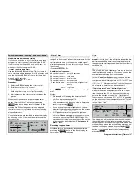
Timers in the basic display
As standard the basic transmitter display contains
four timers. In addition to the transmitter operating
time and the model operating time on the left-hand
side of the screen you will fi nd an “upper” and a “cen-
tre” timer on the right-hand side:
Model name
#01
H-J.Sandbrunner
10.2V
0:30h C62
0
0
0
0
Stop watch
Flight tim
0 00
0 00
:
:
0:30h SPCM20
An additional timer display can be programmed, de-
pending on your settings in the two menus »
Flight
phase timers
« (see page 108) and »
Phase set-
tings
« (see pages 100 / 102). This optional fl ight pha-
se timer appears above the
GRAUPNER/JR
logo or
the fl ight phase name:
Model name
#01
H-J.Sandbrunner
10.2V
0:30h C62
0
0
0
0
Stop watch
Flight tim
Clk 1
«Dist.
»
0 00
0 00
:
:
0.0s
0:30h SPCM20
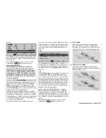
To set the “upper” and “centre” timers hold the rotary
control pressed in and select the appropriate line of
the display:
Model time
Batt. time
Stop watch
Flight tim
CLR
2 : 41h
5 : 03h
0:00
0s
0:00
0s
Timer
Alarm
Top :
Centr:
“Model time”
This timer displays the total recorded time for the cur-
rently active model memory. If you wish, you can as-
sign a switch on the right-hand side of the screen, in
Program description:
Timers
which case the switch is used to record the time auto-
matically: you switch the “Model time” timer on and off
when needed. A brief press on the rotary control with
the
CLR
fi eld highlighted resets the display to “0:00h”.
“Battery time”
This operating hours timer records the total time that
the transmitter has been switched on since the last
time the battery was charged; it is a useful aid in mo-
nitoring the state of the transmitter battery. A switch
cannot be assigned to this function.
This timer is automatically reset to “0:00h” when the
transmitter detects that the voltage of the battery is si-
gnifi cantly higher than the last time it was switched
on, e. g. as a result of a charge process or the instal-
lation of a replacement battery.
Highlight the
CLR
fi eld, then a short press on the ro-
tary control resets the display to “0:00h”.
“Top” and “Centr”
These two timers (count-up or count-down) are loca-
ted in the top right-hand corner of the basic display
(see the top two screen-shots on the left-hand side of
the page). As an option they can be assigned a diffe-
rent name; their function and mode of operation vari-
es according to the name you give them.
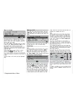
Select the “Top” or “Centr” line:
1
:
30
90s
Alarm
SEL
SEL
SEL
3 : 33h
5 : 55h
Timer
0:00
SEL
Model time
Batt. time
Stop watch
Flight tim
Top :
Centr:
Use the rotary control to activate the left-hand
SEL
fi eld, and after a brief press on the rotary control se-
lect the desired timer function in the highlighted fi eld.
Its name is then superimposed in the basic display.
“Stop watch” and “Motor run”
Both these timer variants can be started and stop-
ped using any of the available switches. To assign a
switch, move to the switch symbol fi eld at the bottom
edge of the screen, and carry out the assignment as
described on page 32.
After you have stopped the timer, pressing
CLEAR
at
the basic display resets it to the programmed starting
value; see below in the sections entitled “Alarm” and
“Timer”.
“Flight time”
The purpose of this timer is to record the fl ight time,
and it can be started using an assigned switch. With
the switch open it can be stopped again by pressing
ESC
at the basic display; press
CLEAR
to reset it to
the starting value once stopped. If you wish to assign
a control switch to this timer, you must fi rst defi ne it in
the »
Control switch
« menu, and determine the swit-
ching point along the travel of the transmitter control.
For example, this might be the start signal when an
electric motor is switched on; alternatively you could
use the throttle limiter in the case of a model helicop-
ter.
“Frame time”
The slot timer is primarily intended for competition pi-
lots, to whom a time “slot” is often assigned within
which a particular task has to be completed. The ti-
mer is started in exactly the same manner as the
fl ight timer, but it can only be stopped by pressing the
ESC
button with the rotary control pressed in, when
the timer switch itself is in the OFF position.
Note:
Note that the timer switches are also active during the
programming procedure.
The “upper” and “centre” timers can be programmed
as count-up or count-down timers, regardless of the
function name you assign to them.
Содержание mx-24s
Страница 1: ...1...
Страница 19: ...19 For your notes...
Страница 35: ...35 For your notes...
Страница 41: ...41 41 For your notes...
Страница 57: ...57 For your notes...
Страница 63: ...63 63 For your notes...
Страница 69: ...69 69 For your notes...
Страница 85: ...85 85 For your notes...
Страница 99: ...99 For your notes...
Страница 143: ...143 For your notes...
Страница 191: ...191 For your notes...
Страница 212: ...212 212 For your notes...
Страница 213: ...213 213 For your notes...
Страница 214: ...214 For your notes...
Страница 216: ...216...


