GRAUPNER GmbH & Co. KG D-73230 KIRCHHEIM/TECK GERMANY
Keine Haftung für Druckfehler. Technische Änderungen vorbehalten!
5/2007
Made in Czech Republic
Ident-Nr.0057273
18
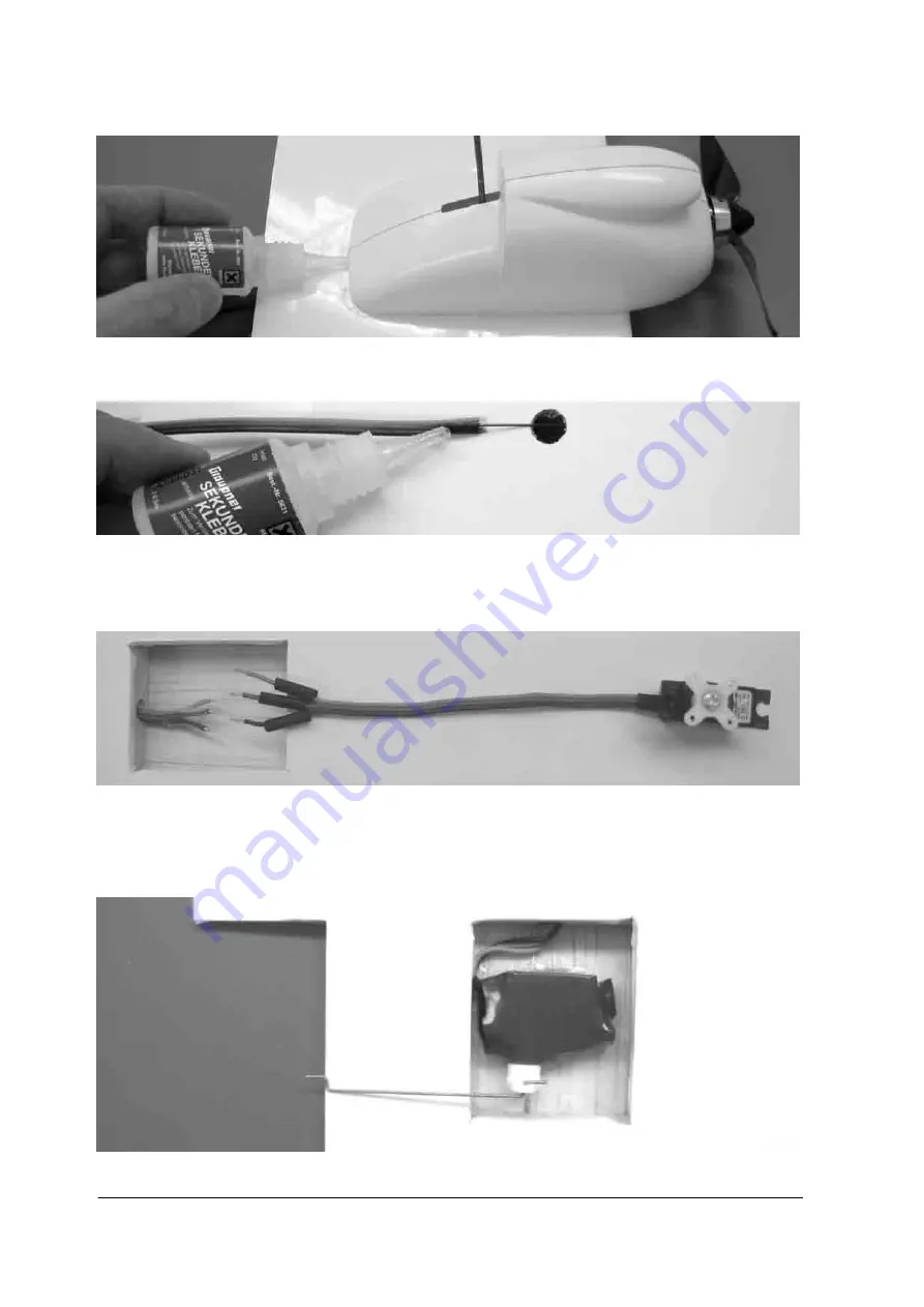
leg through the slot in the nacelle, and fit the nacelle on the wing. Check that the moulding is a snug fit, without gaps.
If this is not the case, remove the nacelle again and sand the edges to obtain a close fit.
Check carefully that the nacelles are positioned exactly correctly, then run cyano along the joints. Spray activator
along the joint line.
The servo extension leads now have to be threaded through the wing. This is easiest to do using a control surface
pushrod (0.6 mm Ø steel wire) as an aid: slip the pushrod into the guide sleeve from the outboard end. Pick up the
end using a pair of tweezers, and pull it through the hole in the centre of the wing. Tack the servo extension lead to
the wire pushrod using cyano, then pull the lead through. Separate the pushrod, then tape the end of the extension
lead to the wing to prevent it slipping back inside the structure.
Cut off the connector at the servo end of the servo lead. Strip the wire ends, fit short pieces of heat-shrink sleeve onto
the separate wires, and solder the wires of the servo lead to those of the extension lead, taking great care to match up
the insulation colours correctly. Remove the servo output lever by undoing the retaining screw, and place the servo in
a piece of heat-shrink sleeve (40 x 40 mm unshrunk - supplied in the kit). Shrink the sleeve round the servo, then cut it
away to reveal the servo output shaft. Set the servo to centre from the transmitter, then re-fit the output lever and
retaining screw.
Connect the aileron pushrod, and position the servo in the servo well exactly as shown: the servo should be central in
the recess, and the pre-formed end of the pushrod should line up exactly with the leading edge of the aileron.


