background image

2

Setting Up Your Kaleido-MX Multiviewer

Introduction

Viewer is available for all multiviewer models, except Kaleido-IP (for which it is not 
relevant).

A Kaleido-MX multiviewer system in its default configuration includes a number of layout presets. Each 
preset shows the video signals from a specific input module (card). Refer to the 

Kaleido-X User’s Manual

 (on 

the DVD that shipped with your multiviewer) for instructions on how to create rooms and layouts according 
to your specific requirements.

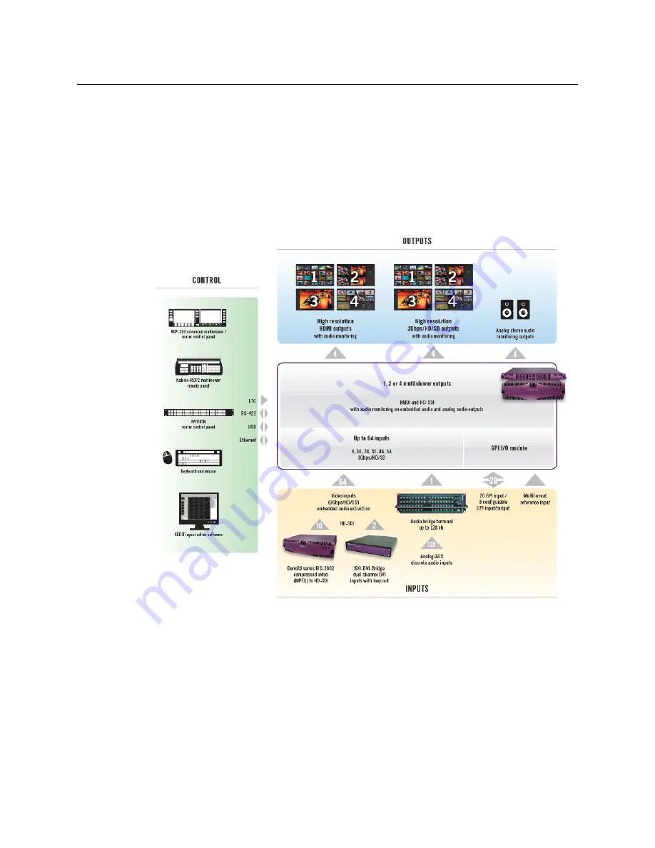
The diagrams below show a Kaleido-MX system with its inputs and outputs. Examples of 
the various external devices that connect to the Kaleido-MX are also shown. A control panel 
would be located on the production desk, while the client PC could be anywhere with 
Internet access to the network.

Kaleido-MX system overview

USO 

RESTRITO

Содержание KALEIDO-MX 3RU

Страница 1: ...Quick Start Guide M933 7105 104 2 April 2015 KALEIDO MX 3RU HIGH QUALITY PRE CONFIGURED MULTIVIEWER USO RESTRITO ...

Страница 2: ...ers to use their product manuals for their own internal business use Manuals for Grass Valley products may not be reproduced or transmitted in any form or by any means electronic or mechanical including photocopying and recording for any purpose unless specifically authorized in writing by Grass Valley A Grass Valley manual may have been revised to reflect changes made to the product during its ma...

Страница 3: ...aking any other equipment connections Identifies an external protective grounding terminal which may be connected to earth ground as a supplement to an internal grounding terminal Indicates that static sensitive components are present which may be damaged by electrostatic discharge Use anti static procedures equipment and surfaces during servicing Indicates that the equipment has more than one pow...

Страница 4: ... aerosol cleaners use only a damp cloth Dangerous voltages may exist at several points in this equipment To avoid injury do not touch exposed connections and components while power is on High leakage current may be present Earth connection of product is essential before connecting power Prior to servicing remove jewelry such as rings watches and other metallic objects To avoid fire hazard use only...

Страница 5: ...curs when electronic components are improperly handled and can result in intermittent failure or complete damage adversely affecting an electrical circuit When you remove and replace any card from a frame always follow ESD prevention procedures Ensure that the frame is electrically connected to earth ground through the power cord or any other means if available Wear an ESD wrist strap ensuring tha...

Страница 6: ...exte doit être remplacé par un fusible du même calibre Identifie une borne de mise à la terre de protection Il faut relier cette borne à la terre avant d effectuer toute autre connexion à l équipement Identifie une borne de mise à la terre externe qui peut être connectée en tant que borne de mise à la terre supplémentaire Signale la présence de composants sensibles à l électricité statique et qui ...

Страница 7: ...les connecteurs Coupez l alimentation avant de nettoyer l équipement Ne pas utiliser de nettoyants liquides ou en aérosol Utilisez uniquement un chiffon humide Des tensions dangereuses peuvent exister en plusieurs points dans cet équipement Pour éviter toute blessure ne touchez pas aux connexions ou aux composants exposés lorsque l appareil est sous tension Avant de procéder à toute opération d en...

Страница 8: ...ns autres que celles qui sont décrites dans le présent manuel sauf si vous êtes qualifié pour le faire Confiez les réparations à un technicien qualifié La maintenance doit se réaliser dans un milieu libre d électricité statique L appareil peut comporter plus d un cordon d alimentation Afin de prévenir les chocs électriques débrancher tous les cordons d alimentation avant toute opération d entretie...

Страница 9: ...u moment de vous en débarrasser veillez à ce que le cristal liquide n entre pas en contact avec la peau ou la bouche En cas de contact avec la peau ou les vêtements laver immédiatement à l eau savonneuse Ne jamais ingérer le liquide La toxicité est extrêmement faible mais la prudence demeure de mise en tout temps Recycling Visit www grassvalley com for recycling information Certification and Compl...

Страница 10: ...N 61000 4 5 Surge transient immunity EN 61000 4 6 Conducted disturbances immunity EN 61000 4 11 Voltage dips short interruptions and voltage variations immunity Note This equipment has been tested and found to comply with the limits for a Class A digital device pursuant to Part 15 of the FCC rules These limits are designed to provide reasonable protection against harmful interference when the equi...

Страница 11: ...QUAD frames as well as the Kaleido Modular X cards and the Kaleido Modular KMV 3901 3911 cards The Kaleido MX standalone multiviewer system is ideal for production control rooms trucks and outside broadcast operations Available in two form factors 1RU and 3RU the Kaleido MX supports up to 64 video inputs and up to four multiviewer outputs At the heart of every multiviewer system is the Kaleido X s...

Страница 12: ...e card Refer to the Kaleido X User s Manual on the DVD that shipped with your multiviewer for instructions on how to create rooms and layouts according to your specific requirements The diagrams below show a Kaleido MX system with its inputs and outputs Examples of the various external devices that connect to the Kaleido MX are also shown A control panel would be located on the production desk whi...

Страница 13: ...es and 1 or 2 power supplies A REF 1801 HD SD frame reference module the second power supply and a second GPI 1501 module are optional The table below indicates how the cards included in your Kaleido MX 3RU are distributed in the housing frame Slot Card Card model Applies to 1 GPI I O 1 GPI 1501 All 3RU configurations 2 GPI I O 2 GPI 1501 All 3RU configurations optional 4 Input D KMX 3901 IN 16 Q ...

Страница 14: ...cond pair of serial port adapters The Kaleido MX 3RU Quick Start Guide this document 15 Input A KMX 3901 IN 16 Q 32 4 48 4 64 4 KMX 3901 IN 16 D 32 2 48 2 64 2 17 Output B KMX 3901 OUT D 32 4 48 4 64 4 19 Output A KMX 3901 OUT D All 3RU configurations Note Removing more than one input card at a time from a Kaleido MX system in operation is not supported 3RU model WECO connectors 32 2 3 32 4 5 48 2...

Страница 15: ...e Notes are available on the DVD that shipped with your multiviewer See the Documentation section of the Release Notes for a complete list You can obtain the latest version of the manuals the Release Notes as well as software and useful data from the Software and documentation section of Grass Valley s support portal Cable type Purpose CAT 5 For Ethernet connectivity Display cables To connect the ...

Страница 16: ...g or removing cards The Kaleido MX starts up The startup sequence takes approximately four minutes during which time every card s status LED is blinking orange Once the startup has completed the status LEDs on the output cards should be red steady because the cards are not connected to the network yet Memory At least 2 GB of RAM Disk space At least 2 GB free Note For more information on the card s...

Страница 17: ... does not support rotated displays Refer to Creating a 4K UHD Room and to 4K UHD Spanning in the Red Firmware initialization in progress no Ethernet SD card error Blinking red Fan failure no rear duplicate IP address Notes The Kaleido RCP2 and Audio Bridge Terminal ABT are optional devices and may not have been shipped with your Kaleido MX system For information on these and other Kaleido MX optio...

Страница 18: ...ailable the system will fall back to the reference signal distributed by the REF 1801 through the URS 7 If you intend to use the GPI interface refer to the Kaleido MX 3RU Guide to Installation and Operation to make the necessary connections to GPI I O 1 and to GPI I O 2 if your order includes a second GPI 1501 card 8 Connect the controller card s ETHERNET 1 port to your Ethernet switch see Cabling...

Страница 19: ...l control panel press the button twice until RESOLUTION appears on the LCD display IMPORTANT Make sure to connect your Densité controller and output cards to the same subnet and that your Ethernet switch remains isolated from the rest of your network consult your network administrator if necessary until all required networking setup is complete IMPORTANT Within a Kaleido MX system all output heads...

Страница 20: ...if available then press the button HEAD 2 appears on the LCD display and you can repeat step 4 to step 8 above to verify or configure the resolution of the display that is connected to the multiviewer s output head 2 i e through the MV OUT 2 connector 10 When you are satisfied with the selected output resolution settings press the Select button on the front edge of the output card to exit the cont...

Страница 21: ...he Kaleido MX multiviewer to join a TCP IP network it must be configured with a system name appropriate IP addresses network mask and gateway settings You must also Video input connections Kaleido RCP2 Client PC or laptop for XEdit XAdmin Ethernet switch HDMI outputs to displays AudioBridge Terminal Kaleido MX 3RU rear USO RESTRITO ...

Страница 22: ...s enabled see Enabling the CPU ETH2 Automatic Restore Feature on page 14 3 Configure your output cards networking parameters If you have a quad head Kaleido MX replace the system IP address network mask default gateway and both output cards IP addresses as appropriate See Configuring the Network Settings for a Quad Head Kaleido MX on page 17 The system IP address will be your system s virtual IP a...

Страница 23: ... status see Step 3 XEdit Installation on page 27 and Step 4 System Verification on page 31 Setting a Densité CPU ETH2 Controller s IP Address To set the Densité controller s IP address 1 On the Kaleido MX frame s local control panel press the CONTROLLER button 2 Press the button repeatedly until ETH1 OPTIONS appears on the display and then press the SEL button 3 Press the button repeatedly until I...

Страница 24: ... ACTION appears on the display and then press the SEL button If the control panel s display shows UPDATE SETTINGS then the automatic restore feature is already enabled If the control panel s display shows KEEP SETTINGS navigate to UPDATE SETTINGS by pressing the button and then press the SEL button to apply your change 4 Press the CONTROLLER button to exit the controller s menu Configuring the Net...

Страница 25: ...e SEL button FRAME IP ADDRESS EDIT appears on the display 3 Press the button to skip this option the system will automatically receive the IP address you configure for Output A once the card will have restarted NETMASK EDIT appears on the display 4 Press the SEL button The current value appears on the display Press the and buttons to change the digit at the current input position Press SEL to move...

Страница 26: ...play 14 Repeat step 4 and step 5 to configure the IP address for Output A 15 Once you have set the IP address for Output A press the Select button on the front edge of the output card to exit the control menu After a moment the card restarts The startup sequence takes approximately four minutes during which time the Status LED is first red and then blinking orange Note Pressing ESC when the input ...

Страница 27: ...gs for a Quad Head Kaleido MX To configure the network settings for a Kaleido MX with two output cards 1 Press the Select button on the front edge of one of your system s output cards The Status LED on the selected card flashes orange and the associated control menu appears on the display of the Densité frame s local control panel 2 On the local control panel press the button repeatedly until NETW...

Страница 28: ...s on the control panel s display 8 Repeat step 3 and step 4 to configure the gateway 9 Once you have configured the gateway and navigated back to the previous menu level press the button again LINK MODE EDIT appears on the control panel s display 10 Press the SEL button 11 The current link mode Auto negotiate appears on the LCD display 12 If your network s mode of operation requires you to change ...

Страница 29: ...ould a Status LED indicate an error condition refer to your Kaleido MX 3RU Hardware Description Installation Manual to find out what the other LEDs might be indicating 20 Verify that both cards and the system s new IP addresses are effective by referring to Verifying the Multiviewer s IP Addresses and Application Version on page 35 Setting the System Name Once you have configured the output cards ...

Страница 30: ... see a security warning or a certificate error message then refer to Registering your Multiviewer s Security Credentials with your Browser in the Kaleido X User s Manual 6 If the Log in to XAdmin page appears type the password and then click Log in 7 Internet Explorer users If a blank page appears then refer to Enabling the Compatibility View in Internet Explorer 10 in the Kaleido X User s Manual ...

Страница 31: ...t for example when using a remote control panel such as the Kaleido RCP2 or RCP 200 Only lower ASCII characters are allowed in the system name Braces and tilde are not allowed 10 Click Save The new settings are saved locally and XAdmin reminds you to click Apply Setting before closing your session Note Under Ethernet you may review the IP addresses network mask gateway settings and the detected co...

Страница 32: ...ver can be found the Kaleido RCP2 will fall back to its default static IP address subnet mask and gateway settings Note Settings cannot be applied to a multiviewer system while an upgrade is in progress If the multiviewer does not restart after 10 seconds or so try clicking Apply settings again after a minute or two Note The Kaleido RCP2 unit is optional and is not included in the standard Kaleido...

Страница 33: ...mouse is connected to the Kaleido RCP2 then you should be able to see and move the mouse pointer on the monitor wall 9 Press any of the LAYOUT PRESETS buttons to load a predefined layout on the monitor wall If your system was configured prior to shipment then a layout will appear on all displays Otherwise a gray screen will appear with the following message in the middle No layout has been assigne...

Страница 34: ... network settings 3 Apply power to the Audio Bridge Terminal and make sure it is connected to the same switch as the PC If the switch is Power over Ethernet PoE enabled simply connect it to the unit using an Ethernet cable If not PoE mid span inserter equipment must be placed between the switch and the Audio Bridge Terminal 4 Press the RESET button located on the right hand side of the ABT rear pa...

Страница 35: ...s 7 or Windows 8 system For Windows XP see Changing an IP Address on Windows XP on page 27 Changing an IP Address on Windows 7 or Windows 8 To change the IP address of a client PC that has Windows 7 or Windows 8 1 Press the Windows key on your keyboard type control panel and then press Enter Subnet mask 255 255 0 0 Default gateway 10 0 0 1 Notes The Kaleido MX supports one ABT device With a 3RU mo...

Страница 36: ...rnet and then click Properties If the system prompts you for an administrator password or confirmation type the password or provide confirmation The Properties window for the selected network adapter opens 4 On the Networking tab under This connection uses the following items click Internet Protocol Version 4 TCP IPv4 and then click Properties The Internet Protocol Version 4 TCP IPv4 Properties wi...

Страница 37: ...indow opens 4 On the General tab click Use the following IP address 5 Type an IP address in the same range as the multiviewer s current IP address For example if the multiviewer s IP address is 10 0 3 70 then the IP address of your client PC could be 10 0 3 123 If you are unsure contact your network administrator 6 Type a subnet mask in the same range as that of the multiviewer 7 Click OK 8 In Loc...

Страница 38: ... browser s security features warnings may appear which you may safely dismiss 3 Unless your browser let you run the file and you chose to do so navigate to the location were you saved the installer file and open it More security warnings or prompts may appear which you may safely dismiss or accept A window appears showing the download and installation progress At the end of the installation proces...

Страница 39: ...nstallation has completed the XEdit startup screen appears Depending on your Windows Firewall settings a security alert may appear Click Allow access to unblock the application If XEdit cannot find all of the fonts it needs already on your PC or laptop it downloads them from the multiviewer automatically in which case a message will appear to confirm the font update and instruct you to restart the...

Страница 40: ...dow appears For more information about calibrating your system configuring rooms creating layouts and operating the monitor wall refer to the Kaleido X User s Manual available on the DVD that shipped with your system and from Grass Valley s support portal Note Once it has been installed from the multiviewer XEdit remains on your PC or laptop and can be launched from the shortcut that was added to ...

Страница 41: ...figured at step 4 on page 18 in the case of a quad head system in the address bar The Kaleido X home page appears 2 Click the XAdmin button 3 If you see a security warning or a certificate error message then refer to Registering your Multiviewer s Security Credentials with your Browser in the Kaleido X User s Manual 4 If the Log in to XAdmin page appears type the password and then click Log in 5 I...

Страница 42: ...the navigation area on the left of the page The Physical Connections page appears showing the current connection status for your system with a visual representation of the physical connections between the detected input cards and the output cards associated with the frame IP address USO RESTRITO ...

Страница 43: ...here a problem was detected 8 Click Status and options in the navigation area on the left of the page to go back to the Status and Options page The module headings show the card type and serial number for the input and output cards and a summary view of the input signals for each input card 9 Move the pointer to an input signal status icon to view the associated signal format USO RESTRITO ...

Страница 44: ...rious operations using the Kaleido RCP2 keyboard and the mouse e g load a predefined layout Loading a Layout To load a layout on the monitor wall 1 Connect a mouse to the Kaleido RCP2 if available and log on to the appropriate room if you have not already done so see Using the Kaleido RCP2 with Default Settings on page 22 Notes At any time you can click the Refresh button to make sure the data dis...

Страница 45: ...nd side of the rear panel This LED reports the status of the Ethernet connection as indicated in the table below Two LEDs are visible on the front panel one for each power supply When lit they both indicate the same status When the ABT is powered up all three LEDs will be orange until the boot sequence is terminated This is a visual indicator that the LEDs are functioning properly Verifying the Mu...

Страница 46: ...ge and the associated control menu appears on the display of the Densité frame s local control panel 2 Note the position indication A or B in the card information shown on the first line of the LCD display either KMX OUTA or KMX OUTB followed with the slot number e g KMX OUTA Slot 4 3 On the local control panel press the button The version of the Kaleido X Software that is running on the card e g ...

Страница 47: ...control menu RS 422 Connection Diagram Each output card supports one RS 422 serial port over an RJ 45 connector This port allows the Kaleido MX to connect to external serial devices such as a router production switcher or router controller The pinout for the RS 422 signals on the RJ 45 connectors and the wiring diagrams for the appropriate adapters are shown here Select button Status LED Note The ...

Страница 48: ... about the RS 422 serial connections see the Serial Connections section in the Routers chapter of the Kaleido X User s Manual Note The two RS 422 ports on the multiviewer side have no ground pin Using the appropriate DE 9S to RJ 45 adapter an external device should be able to communicate with a multiviewer despite the lack of a ground Pinout of each RS 422 port s RJ 45 connector on the multiviewer...

Страница 49: ...al phone number for the support center nearest you please consult the Contact Us section of Grass Valley s Web site www grassvalley com An online form for e mail contact is also available from the Web site Corporate Head Office Grass Valley 3499 Douglas B Floreani St Laurent Quebec H4S 2C6 Canada Telephone 1 514 333 1772 Fax 1 514 333 9828 www grassvalley com USO RESTRITO ...

Отзывы: