
48
S
YSTEM
T
ROUBLESHOOTING
NOTE:
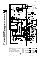
Refer to the instructions accompanying the ComfortNet
compatible outdoor AC/HP unit for troubleshooting information.
Refer to the Troubleshooting Chart in the back of this manual for
a listing of possible furnace error codes, possible causes and
corrective actions.
N
ORMAL
S
EQUENCE
OF
O
PERATION
P
OWER
U
P
The normal power up sequence is as follows:
•
115 VAC power applied to furnace.
•
Integrated control module performs internal checks.
•
Integrated control module displays
88888 88888
on dual 7-segment
display LED’s.
•
Integrated control module monitors safety circuits
continuously.
•
Furnace awaits call from thermostat. Dual 7-segment LED’s
display
OOOOO
while awaiting call from thermostat.
H
EATING
M
ODE
The normal operational sequence in heating mode is as follows:
•
R and W1 (or R and W1/W2) thermostat contacts close,
initiating a call for heat.
•
Integrated control module performs safety circuit checks.
•
Induced draft blower is energized on high speed for a 15-
second prepurge. Humidifier terminal is energized with
induced draft blower.
•
Induced draft blower steps to low speed following prepurge.
Low stage pressure switch contacts are closed.
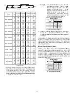
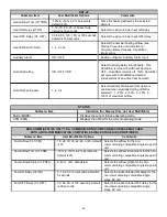
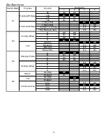
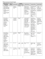
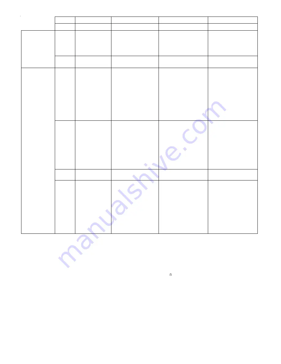
LED
Description
Off
Normal condition
Red
Communications
LED
1 Flash
Communications
Failure
2 Flashes Out-of-box reset
Green Receive
LED
Off •Nopower
•Communications
error
1 Steady
Flash
No network
found
Rapid
Flashing
Normal network
traffc
On Solid
Data 1/ Data 2
miss-wire
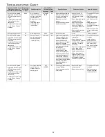
Possible Cause
Corrective Action
Comments
None
None None
Communications
Failure
•Depress Learn Button
•Verify that bus BIAS and
TERM dipswitches are in
the ON position.
•Depress once quickly for
a power-up reset
•Depress and hold for 2
seconds for an out-of-box
reset
•Control power up
•Learn button depressed
None
None
•No power to furnace
•Open fuse
•Communications error
•Check fuses and circuit
breakers; replace/reset
•Replace blown fuse
•Check for shorts in low
voltage wiring in furnace/
system
•Reset network by
depressing learn button
•Check data 1/ data 2
voltages
•Turn power OFF prior to
repair
•Broken/ disconnected
data wire(s)
•Furnace is installed
as a legacy/ traditional
system
•Check communications
wiring (data 1/ data 2
wires)
•Check wire connections
at terminal block
•Verify furnace installation
type (legacy/ traditional
or communicating) Check
data 1/ data 2 voltages
•Turn power OFF prior to
repair
•Verify wires at terminal
blocks are securely
twisted together prior to
inserting into terminal
block
•Verify data1 and data
voltages as described
above
Control is “talking” on
network as expected
None
None
•Data 1 and data 2 wires
reversed at furnace,
thermostat, or CT™
compatible outdoor AC/
HP
•Short between data 1
and data 2 wires
•Short between data 1
or data 2 wires and R
(24VAC) or C (24VAC
common)
•Check communications
wiring (data 1/ data 2
wires)
•Check wire connections
at terminal block
•Check data 1/ data 2
voltages
•Turn power OFF prior to
repair
•Verify wires at terminal
blocks are securely
twisted together prior to
inserting into terminal
block
•Verify data1 and data
voltages as described
above


