
37
FI
LT
ER
AIR FLOW
CENTRAL
RETURN
GRILLE
RETURN
DUCT
FI
LT
E
R
FILTER
SUPPORT
BRACKET
(Field Supplied)
FILTER
ACCESS
DOOR
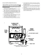
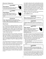
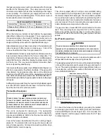
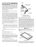
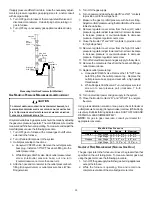
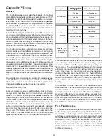
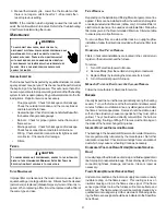
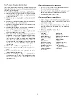
Possible Upright Counterflow
Filter Locations
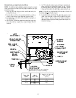
H
ORIZONTAL
I
NSTALLATIONS
Filters must be installed in either the central return register or in
the return air duct work.
S
TARTUP
P
ROCEDURE
& A
DJUSTMENT
Furnace must have a 115 VAC power supply properly connected
and grounded. Proper polarity must be maintained for correct
operation. In addition to the following start-up and adjustment
items, refer to further information in
Operational Checks
section.
H
EAT
A
NTICIPATOR
S
ETTING
The heat anticipator in the room thermostat must be correctly
adjusted to obtain the proper number of cycles per hour and to
prevent “overshooting” of the setting. Set the heat anticipator set-
ting to 0.7 amps. Follow the thermostat manufacturer’s instruc-
tions on how to adjust the heat anticipator setting.
D
RAIN
T
RAP
P
RIMING
The drain trap must be primed prior to furnace startup. To prime, fill
the drain trap with water. This ensures proper furnace drainage
upon startup and prohibits the possibility of flue gases escaping
through the drain system.
F
URNACE
O
PERATION
Purge gas lines of air prior to startup. Be sure not purge lines into
an enclosed burner compartment.
Check for leaks using an approved chloride-free soap and water
solution, an electronic combustible gas detector, or other approved
method. Verify that all required kits (propane gas, high altitude,
etc.) have been appropriately installed.
F
URNACE
S
TARTUP
1. Close the manual gas shutoff valve external to the furnace.
2. Turn off the electrical power to the furnace.
3. Set the room thermostat to the lowest possible setting.
4. Remove the burner compartment door.
NOTE:
This furnace is equipped with an ignition device which
automatically lights the burner. Do not try to light the burner by
hand.
5. Move the furnace gas valve manual control to the OFF
position.
6. Wait five minutes then smell for gas. Be sure check near
the floor as some types of gas are heavier than air.
7. If you smell gas after five minutes, immediately follow the
Safety Instructions
on page 5 of this manual. If you do not
smell gas after five minutes, move the furnace gas valve
manual control to the ON position.
8. Replace the burner compartment door.
9. Open the manual gas shutoff valve external to the furnace.
10. Turn on the electrical power to the furnace.
11. Adjust the thermostat to a setting above room temperature.
12. After the burners are lit, set the thermostat to desired
temperature.
F
URNACE
S
HUTDOWN
1. Set the thermostat to the lowest setting.
The integrated control will close the gas valve and extinguish
flame. Following a 15 second delay, the induced draft blower
will be de-energized. After a 120, 150, 180 or 210-second
delay period (field selectable delay OFF [90, 120, 150, 180]
plus 30-second ramp down), the circulator blower de-
energizes.
2. Remove the burner compartment door and move the furnace
gas valve manual control to the OFF position.
3. Close the manual gas shutoff valve external to the furnace.
4. Replace the burner compartment door.
G
AS
S
UPPLY
P
RESSURE
M
EASUREMENT
G
AS
P
RESSURE
T
EST
This test is to be used for field test mode only, and it will allow
gas valve pressure to be checked at 100% firing rate.
1. If both ‘FAULT RECALL’ and ‘LEARN’ push buttons are
pressed for greater than 1 second, the display will blank to
indicate the push buttons are pressed. Within 5 seconds,
both push buttons should be released. If any push button
is not released, the test mode will not activate. The dis-
play will return to normal.
2. Once the push buttons are released, the display will flash
“Ft” to indicate the push buttons are released and suc-
cessful entry into test mode has been achieved.
3. The control will force a high capacity demand. If a low
capacity demand is already being serviced, it will be forced
to high capacity.
4. The display will continue to flash “Ft” until high capacity
(100%) is achieved. Once achieved, the display will show
“Ft” without flashing. A 5-minute timer will be started to
allow sufficient opportunity for the gas pressure to be
tested.


