
15
RUBBER
COUPLING
WITH WORM
GEAR CLAMPS
RUBBER
COUPLINGS
WITH WORM
GEAR CLAMPS
COMBUSTION
AIR PIPE
(DIRECT VENT ONLY)
COMBUSTION
AIR PIPE
(DIRECT VENT ONLY)
VENT/FLUE
PIPE
VENT/FLUE
PIPE
90 PVC
ELBOW
(NON-DIRECT VENT)
90 PVC
ELBOW
(NON-DIRECT VENT)
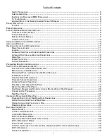
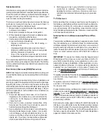
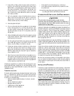
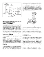
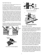
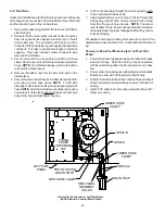
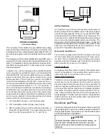
Standard Connections
OR
OR
UPFLOW COUNTERFLOW
A
LTERNATE
F
URNACE
C
ONNECTIONS
If the standard locations are undesirable for a specific installation,
alternate side panel locations are available for both combustion air
inlet and vent/flue pipe connections. These locations may be of
particular benefit to upright upflow installations requiring additional
access to an
A
coil, or to upright counterflow installations requiring
additional access to a filter or electronic air cleaner, or to horizontal
installations desiring vent/flue (and combustion air intake) piping
run vertically from the side of the cabinet.
NOTE:
Standard and alternate locations can be combined (i.e.,
an installation may use the standard combustion air intake loca-
tion but use the alternate vent/flue location or vice versa), if needed.
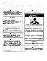
E
DGES
OF
SHEET
METAL
HOLES
MAY
BE
SHARP
.
U
SE
GLOVES
AS
A
PRECAUTION
WHEN
REMOVING
HOLE
PLUGS
.
WARNING
A
LTERNATE
V
ENT
/F
LUE
L
OCATION
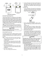
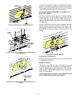
The alternate vent/flue location is the large hole directly
in line with
the induced draft blower outlet. To use the alternate vent/flue loca-
tion refer to the following steps and the “Alternate Vent/Flue Loca-
tion” figure.
NOTE:
Counterflow instructions follow the upflow instructions.
1. Remove and save the four screws securing the vent/flue
coupling to the furnace top panel.
Counterflow
units.
Remove and save the four screws securing the vent/flue
coupling to the furnace basepan. Also remove the three
screws securing the furnace’s internal vent/flue piping to
the blower deck.
2.
Upflow
and
Counterflow
units
.
Loosen the worm gear hose clamps on the rubber elbow
and detach it from both the induced draft blower and the
vent/flue pipe.
3.
Upflow
and
Counterflow
units
.
Remove the vent/flue pipe from the furnace.
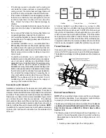
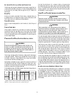
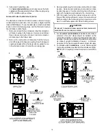
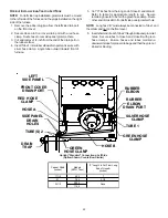
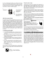
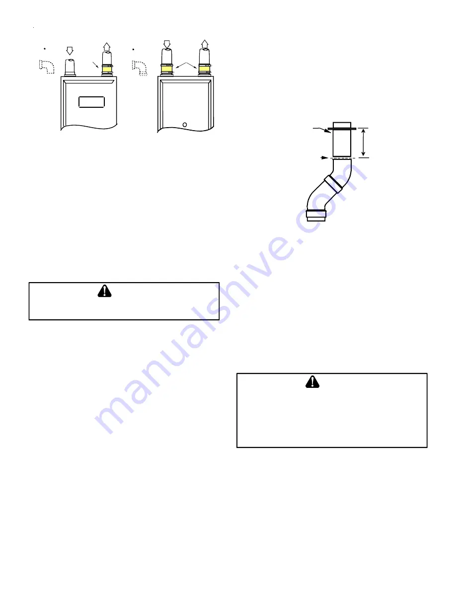
4. Cut the vent/flue pipe 3.75 inches from the flanged end of
the pipe (see “Vent/Flue Pipe Cuts” figure)
.
The section of
pipe attached to the coupling will reach through the side
panel to the induced draft blower. Discard remaining pipe
and elbows.
Counterflow
units.
Cut the vent/flue pipe 3.75 inches from the blower deck
coupling (see “Vent/Flue Pipe Cuts” figure)
.
Save vent/flue
pipe attached to blower deck coupling for use in the alternate
location. Discard remaining pipe and elbows.
FLANGE
CUT
HERE
3.75"
Vent/Flue Pipe Cuts
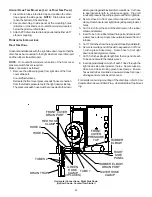
5. Remove plastic plug from alternate vent/flue location.
Relocate and install plug in standard vent/flue location (top
cover).
Counterflow
units.
Remove plastic plug from alternate vent/flue location.
Relocate and install plug in standard vent/flue location
(basepan). Plug remaining hole in blower deck with plastic
plug included in the drain kit bag.
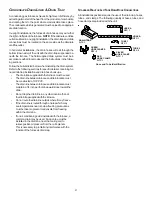
6.
Upflow
and
Counterflow
units
.
Insert cut section of vent/flue pipe and coupling into alternate
vent/flue location. Using a rubber coupling and worm gear
hose clamps from the drain kit bag, attach the vent/flue
pipe and coupling to the induced draft blower. Secure the
coupling to the cabinet using the screws removed in step 1
or with field-supplied 3/8” #8 self drilling screws.
T
HE
RUBBER
ELBOW
IS
NOT
DESIGNED
TO
SUPPORT
A
LOAD
.
W
HEN
THE
RUBBER
ELBOW
IS
MOUNTED
EXTERNALLY
TO
THE
FURNACE
CABINET
,
EXTREME
CARE
MUST
BE
TAKEN
TO
ADEQUATELY
SUPPORT
FIELD
‐
SUPPLIED
VENT
/
FLUE
PIPING
,
AS
DAMAGE
CAN
RESULT
IN
LEAKS
CAUSING
BODILY
INJURY
OR
DEATH
DUE
TO
EXPOSURE
TO
FLUE
GASES
,
INCLUDING
CARBON
MONOXIDE
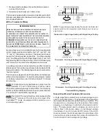
WARNING
7.
Upflow
and
Counterflow
units
.
For
upright installations
, externally mount the rubber
elbow to the vent/flue coupling using a worm gear hose
clamp. Secure field supplied vent/flue piping to the rubber
elbow using a worm gear hose clamp.
NOTE:
Use of the
alternate vent/flue location for upright installations, requires
the drain trap be installed on the same side of the unit as
the flue pipe.


