
42
OFF
OFF
Model
Tap
Low Stage
Cool
High Stage
Cool
Low Stage
Heat
High Stage
Heat
A
390
600
581
818
B
520
800
644
919
C
650
1000
711
1022
D
780
1200
795
1134
A
390
600
840
1210
B
520
800
920
1325
C
715
1100
1000
1440
D
929
1429
1080
1555
A
550
810
1050
1490
B
770
1100
1120
1570
C
1000
1470
1200
1690
D
1250
1810
1250
1780
A
520
800
1125
1620
B
715
1000
1195
1721
C
910
1400
1265
1822
D
1170
1800
1335
1922
A
520
800
1230
1771
B
715
1100
1265
1822
C
910
1400
1300
1872
D
1170
1800
1335
1922
A
360
660
870
1230
B
520
830
950
1350
C
780
1130
1040
1470
D
960
1460
1130
1600
A
560
810
1120
1620
B
740
1110
1220
1760
C
920
1430
1280
1860
D
1190
1860
1340
1970
A
508
783
1214
1759
B
690
1091
1229
1791
C
906
1406
1296
1838
D
1165
1809
1302
1878
*MVC950704CX*
*MVC950453BX*
*MVC951155DX*
*MVC950905DX*
*MVC950905CX*
*CVC91155DX*
*CVC950915DX*
*CVC950714CX*
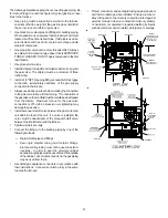
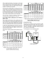
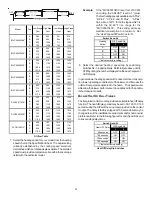
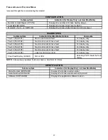
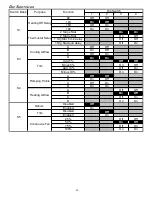
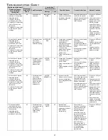
Airflow Table
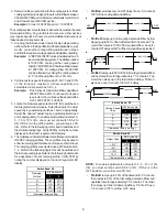
7. Select the heating speed for your model from the heating
speed chart in the Specification Sheet. The adjust setting
(already established by the cooling speed selection)
determines which set of speeds are available. The selected
speed must provide a temperature rise within the rise range
listed with the particular model.
Example:
If the *MVC950704CX is set for 1210 CFM
on cooling, the “ADJUST” is set to “+” (plus).
The four heating speeds available are “A Plus”,
“B Plus”, “C Plus”, and “D Plus”. “A Plus”
has a rise of 46
°
F for both stages which is
within the 30-60°F rise range for the
*MVC950704CX. This setting will keep
electrical consumption to a minimum. Set
the “Heat” speed DIP switches to “A”.
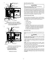
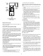
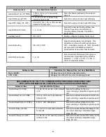
3
4
A
OFF
OFF
B*
ON
OFF
C
OFF
ON
D
ON
ON
Switch Bank: S4
Heating
Airflow
DIP Switch No.
(*Indicates factory setting)
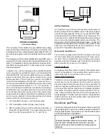
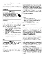
8. Select the desired “heating” speed tap by positioning
switches S4- 3,4 appropriately. Refer to figure above. Verify
CFM by noting the number displayed on the dual 7-segment
LED display.
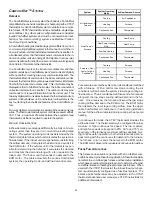
In general lower heating speeds will: reduce electrical consump-
tion, lower operating sound levels of the blower, and increase the
outlet air temperature delivered to the home. The speeds avail-
able allow the blower performance to be optimized for the particu-
lar homeowner’s needs.
B
LOWER
H
EAT
O
FF
D
ELAY
T
IMINGS
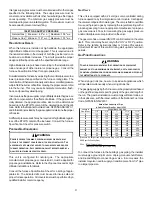
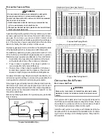
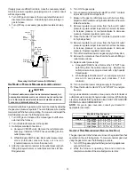
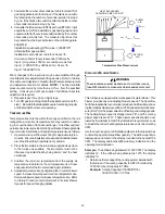
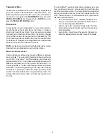
The integrated control module provides a selectable heat off delay
function. The heat off delay period may be set to 90, 120, 150, 180
seconds using the DIP switches or jumper provided on the control
module. The delay is factory shipped at 150 seconds but may be
changed to suit the installation requirements and/or homeowner
preference. Refer to the following figures for switch positions and
corresponding delay times.
1
2
90 seconds
OFF
OFF
120 seconds
ON
OFF
150 seconds *
OFF
ON
180 seconds
ON
ON
Heat OF F Delay
DIP Switch No.
Switch Bank: S1
(*Indic ates factory setting)
Heat Off Delay Dip Switches


