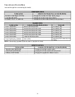
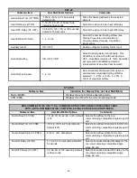

35
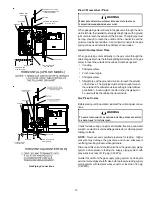
A closed return duct system must be used, with the return duct
connected to the furnace.
NOTE:
Ductwork must never be at-
tached to the back of the furnace.
For upflow installations requir-
ing 1800 CFM or more, use either two side returns or bottom
return or a combination of side /bottom. Flexible joints may be
used for supply and return connections to reduce noise transmis-
sion. To prevent the blower from interfering with combustion air or
draft when a central return is used, a connecting duct must be
installed between the unit and the utility room wall. Never use a
room, closet, or alcove as a return air chamber.
C
HECKING
D
UCT
S
TATIC
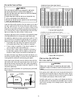
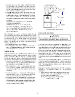
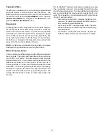
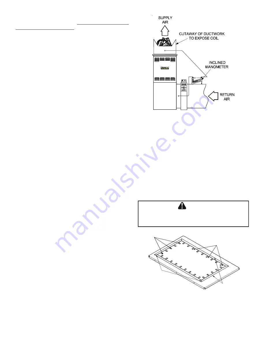
Refer to your furnace rating plate for the maximum ESP (ex-
ternal duct static) rating.
Total external static refers to everything external to the fur-
nace cabinet. Cooling coils, filters, ducts, grilles, registers
must all be considered when reading your total external static
pressure. The supply duct pressure must be read between
the furnace and the cooling coil. This reading is usually taken
by removing the “A” shaped block off plate from the end on the
coil; drilling a test hole in it and reinstalling the block off plate.
Take a duct static reading at the test hole. Tape up the test
hole after your test is complete. The negative pressure must
be read between the filter and the furnace blower.
Too much external static pressure will result in insufficient air
that can cause excessive temperature rise. This can cause
limit switch tripping and heat exchanger failure.
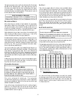
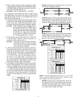
To determine total external duct static pressure, proceed as
follows;
1. With clean filters in the furnace, use a draft gauge (in-
clined manometer) to measure the static pressure of the
return duct at the inlet of the furnace. (Negative Pressure)
2. Measure the static pressure of the supply duct. (Positive
Pressure)
3. The difference between the two numbers is .4” w.c.
Example:
static reading from return duct = -.1" w.c.
static reading from supply duct = .3" w.c.
total external static pressure on this system = .4" w.c.
NOTE:
Both readings may be taken simultaneously and read
directly on the manometer if so desired. If an air conditioner
coil or Electronic Air Cleaner is used in conjunction with the
furnace, the readings must also include theses components,
as shown in the following drawing.
4. Consult proper tables for the quantity of air.
If the total external static pressure exceeds the maximum
listed on the furnace rating plate, check for closed dampers,
registers, undersized and/or oversized poorly laid out duct work.
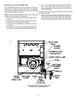
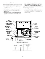
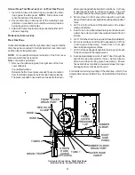
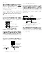
Checking Static Pressure
(80% Furnace Shown, 90% Similar)
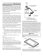
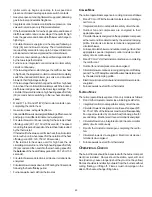
B
OTTOM
R
ETURN
A
IR
O
PENING
[U
PFLOW
M
ODELS
]
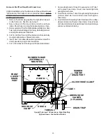
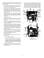
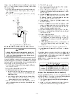
The bottom return air opening on upflow models utilizes a “lance
and cut” method to remove sheet metal from the duct opening in
the base pan. To remove, simply press out the lanced sections by
hand to expose the metal strips retaining the sheet metal over the
duct opening. Using tin snips, cut the metal strips and remove the
sheet metal covering the duct opening. In the corners of the open-
ing, cut the sheet metal along the scribe lines to free the duct
flanges. Using the scribe line along the duct flange as a guide,
unfold the duct flanges around the perimeter of the opening using a
pair of seamer pliers or seamer tongs.
NOTE:
Airflow area will be
reduced by approximately 18% if duct flanges are not unfolded.
This could cause performance issues and noise issues.
E
DGES
OF
SHEET
METAL
HOLES
MAY
BE
SHARP
.
U
SE
GLOVES
AS
A
PRECAUTION
WHEN
REMOVING
SHEET
METAL
FROM
RETURN
AIR
OPENINGS
.
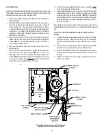
WARNING
CUT FOUR CORNERS
AFTER REMOVING SHEET
METAL
CUT USING TIN SNIPS
PRESS OUT BY HAND
SCRIBE LINES OUTLINING
DUCT FLANGES
Duct Flange Cut Outs
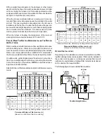
When the furnace is used in connection with a cooling unit, the
furnace should be installed in parallel with or on the upstream side
of the cooling unit to avoid condensation in the heating element.


