
38
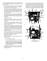
5. If a call for heat is given or removed during the test, the
system will still operate until the 5 minute test time is
complete.
6. During test mode, if both push buttons are pressed for
greater than 1 second, the display will blank to indicate
push buttons are pressed. If both push buttons are re-
leased within 5 seconds, the test mode will terminate and
the system will return to normal operation. Otherwise, the
test mode will continue uninterrupted.
7. After completion of the 5-minute timer or test mode termi-
nation, whichever is earlier, the system will return to nor-
mal operation, either continuing an existing heat demand
or going to the idle state.
CAUTION
T
O
PREVENT
UNRELIABLE
OPERATION
OR
EQUIPMENT
DAMAGE
,
THE
INLET
GAS
SUPPLY
PRESSURE
MUST
BE
AS
SPECIFIED
ON
THE
UNIT
RATING
PLATE
WITH
ALL
OTHER
HOUSEHOLD
GAS
FIRED
APPLIANCES
OPERATING
.
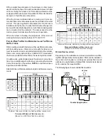
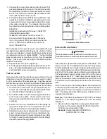
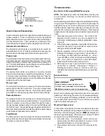
The line pressure supplied to the gas valve must be within the
range specified below. The supply pressure can be measured at
the gas valve inlet pressure boss or at a hose fitting installed in the
gas piping drip leg. The supply pressure must be measured with
the burners operating. To measure the gas supply pressure, use
the following procedure.
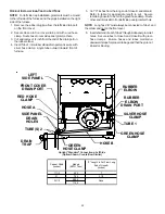
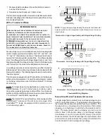
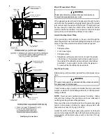
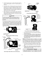
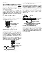
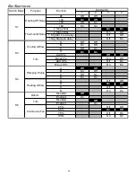
INLET
OUTLET
Gas Valve On/Off
Selector Switch
White-Rodgers Model 36G54 (Two-Stage)
Inlet
Pressure
Boss
Low Fire
Regulator
Adjust
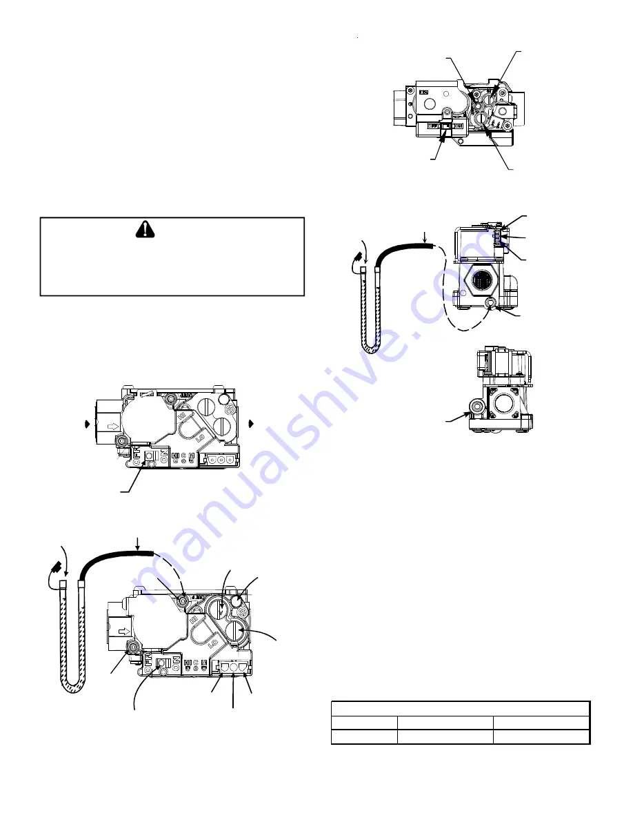
Manometer
Manometer
Hose
High Fire Regulator
Adjust
Regulator
Vent
Outlet
Pressure Boss
Open to
Atmosphere
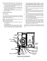
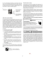
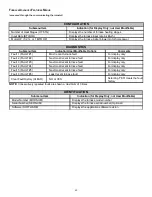
On/Off Switch
High Fire Coil
Terminal (HI)
Coaxial Coil
Terminal (M)
Common
Terminal(C)
White-Rodgers Model 36G54 Connected to Manometer
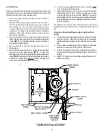
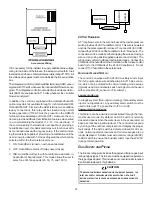
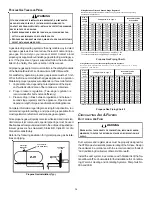
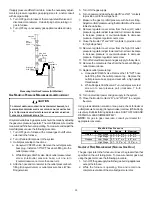
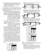
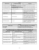
Gas Valve On/Off
Selector Switch
Regulator
Vent
High Fire
Regulator
Adjust
Low Fire
Regulator
Adjust
Honeywell Model VR9205 (Two-Stage)
i
Manometer
Manometer
Hose
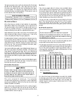
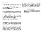
Common
Terminal(C)
High Fire Coil
Terminal (HI)
Low Fire Coil
Terminal (LO)
Inlet Pressure Tap
1/8 NPT
Open to
Atmosphere
Outlet Pressure Tap
1/8 NPT
Honeywell Model VR9205 Connected to Manometer
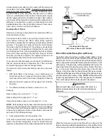
1. Turn OFF gas to furnace at the manual gas shutoff valve
external to the furnace.
2. Connect a calibrated water manometer (or appropriate gas
pressure gauge) at either the gas valve inlet pressure boss
or the gas piping drip leg. See Honeywell VR9205 gas valve
figure or White-Rodgers 36G54 gas valve figure for location
of inlet pressure boss.
NOTE:
If measuring gas pressure at the drip leg or Honeywell
VR9205 gas valve, a field-supplied hose barb fitting must be installed
prior to making the hose connection. If using the inlet pressure
boss on the White-Rodgers 36G54 gas valve, then use the 36G
Valve Pressure Check Kit, Goodman Part No. 0151K00000S.
3. Turn ON the gas supply and operate the furnace and all
other gas consuming appliances on the same gas supply
line.
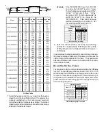
4. Measure furnace gas supply pressure with burners firing.
Supply pressure must be within the range specified in the
Inlet Gas Supply Pressure
table.
Natural Gas
Minimum: 4.5" w.c.
Maximum: 10.0" w.c.
Propane Gas
Minimum: 11.0" w.c.
Maximum: 13.0" w.c.
INLET GAS SUPPLY PRESSURE


