
36
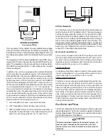
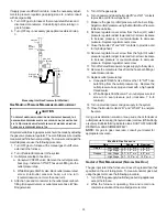
With a parallel flow arrangement, the dampers or other means
used to control the flow of air must be adequate to prevent chilled
air from entering the furnace and, if manually operated, must be
equipped with means to prevent operation of either unit unless the
damper is in the full heat or cool position.
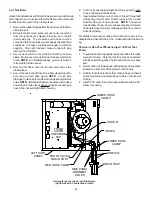
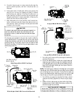
When the furnace is installed without a cooling coil, it is recom-
mended that a removable access panel be provided in the outlet
air duct. This opening shall be accessible when the furnace is
installed and shall be of such a size that the heat exchanger can
be viewed for visual light inspection or such that a sampling probe
can be inserted into the airstream. The access panel must be
made to prevent air leaks when the furnace is in operation.
When the furnace is heating, the temperature of the return air
entering the furnace must be between 55°F and 100°F.
F
ILTERS
- R
EAD
T
HIS
S
ECTION
B
EFORE
I
NSTALLING
T
HE
R
ETURN
A
IR
D
UCT
WORK
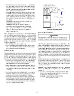
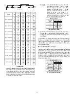
Filters must be used with this furnace. Discuss filter maintenance
with the building owner. Filters do not ship with this furnace, but
must be provided, sized and installed externally by the installer.
Filters must comply with UL900 or CAN/ULCS111 standards. If
the furnace is installed without filters, the warranty will be voided.
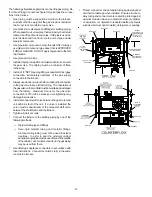
On upflow units, guide dimples locate the side return cutout loca-
tions. Use a straight edge to scribe lines connecting the dimples.
Cut out the opening on these lines.
NOTE:
An undersized open-
ing will cause reduced airflow.
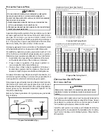
Refer to Minimum Filter Area tables to determine filter area require-
ments.
600
800
1000
1200
1400
1600
1800
2000
0453__X*
207*
207*
240
288
---
---
---
---
0704__X*
---
---
318*
318*
336
384
---
---
0905__X*
---
---
---
413*
413*
413*
432
480
1155__X*
---
---
---
437*
437*
437*
432
480
600
800
1000
1200
1400
1600
1800
2000
0714__X*
---
---
316*
316*
336
384
---
---
0915__X*
---
---
---
409*
409*
409*
432
480
1155__X*
---
---
---
430*
430*
430*
432
480
Input
__Ai
rf
lo
w
UPFLOW
COOLING AIRFLOW REQUIREMENT (CFM)
COUNTERFLOW
COOLING AIRFLOW REQUIREMENT (CFM)
Input
Ai
rf
lo
w
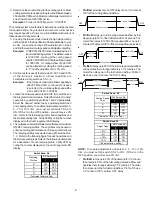
*Minimum filter area dictated by heating airflow requirement
.
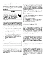
Permanent Minimum Filter Area (sq. in)
[Based on a 600 ft/min filter face velocity]
600
800
1000
1200
1400
1600
1800
2000
0453__X*
415*
415*
480
576
---
---
---
---
0704__X*
---
---
636*
636*
672
768
---
---
0905__X*
---
---
---
826*
826*
826*
864
960
1155__X*
---
---
---
875*
875*
875*
875*
960
600
800
1000
1200
1400
1600
1800
2000
0714__X*
---
---
634*
634*
672
768
---
---
0915__X*
---
---
---
819*
819*
819*
864
960
1155__X*
---
---
---
860*
860*
860*
864
960
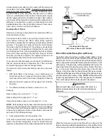
Input__A
irflow
UPFLOW
COOLING AIRFLOW REQUIREMENT (CFM)
COUNTERFLOW
COOLING AIRFLOW REQUIREMENT (CFM)
Input Airflow
*Minimum filter area dictated by heating airflow requirement.
Disposable Minimum Filter area (sq. in)
[Based on 300 ft/min filter face velocity]
U
PRIGHT
I
NSTALLATIONS
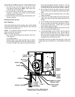
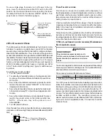
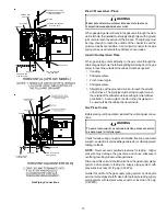
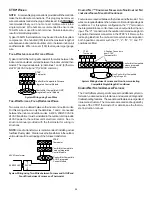
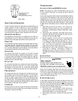
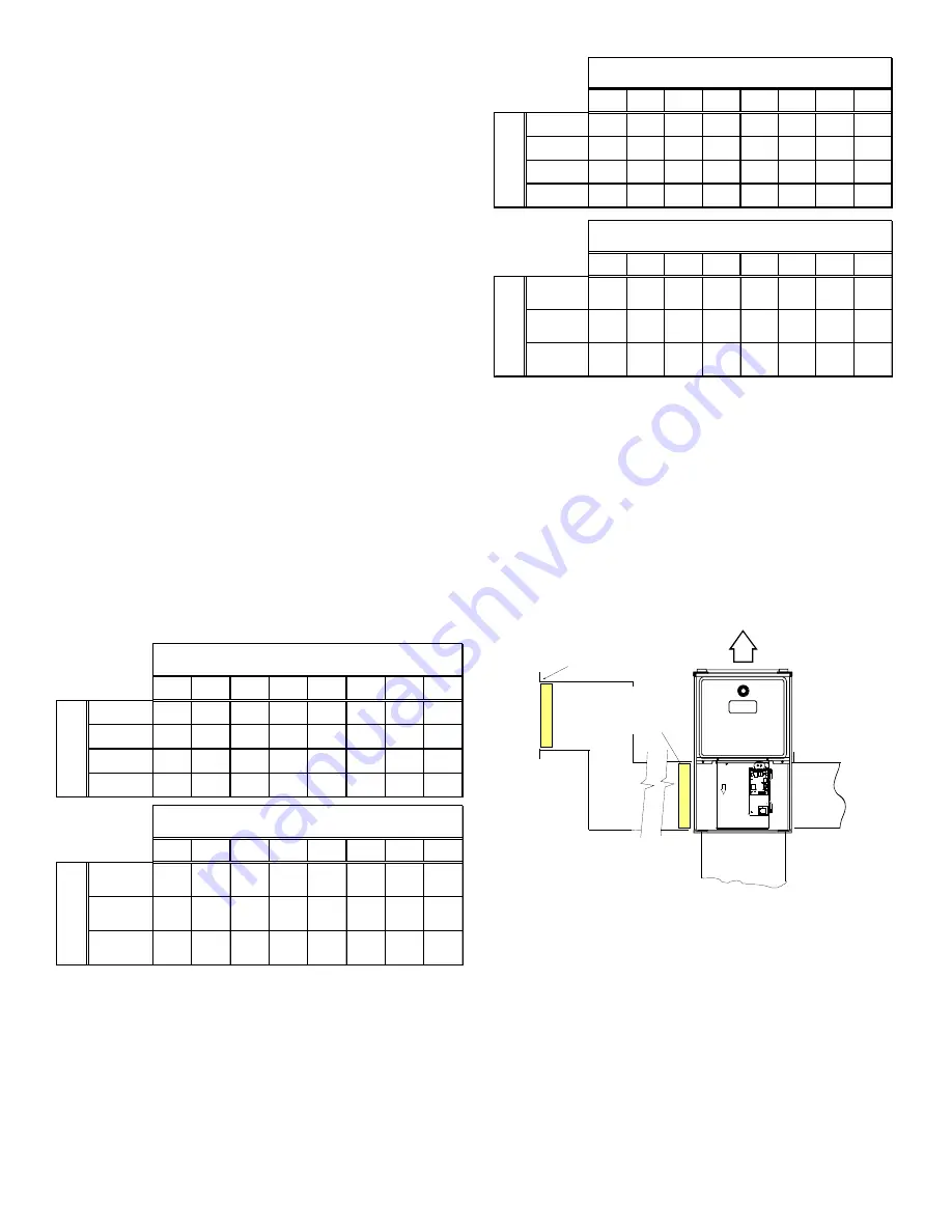
Depending on the installation and/or customer preference, differ-
ing filter arrangements can be applied. Filters can be installed in
the central return register or a side panel external filter rack kit
(upflows). As an alternative a media air filter or electronic air cleaner
can be used as the requested filter.
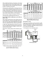
The following figure shows possible filter locations.
FI
L
T
E
R
AIR FLOW
CENTRAL
RETURN
GRILLE
FI
L
T
E
R
SIDE RETURN
EXTERNAL FILTER
RACK KIT
(EITHER SIDE)
Possible Upright Upflow


