30
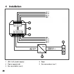
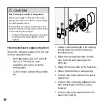
42 V
230 V
1
2
3
4
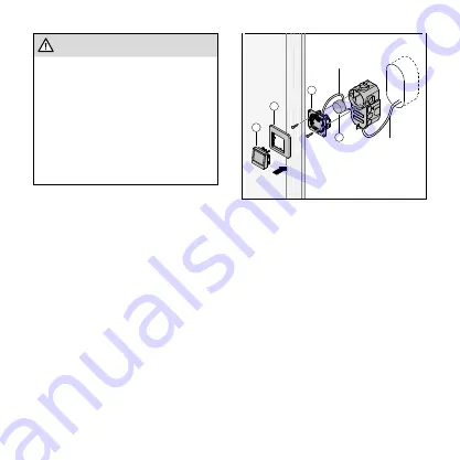
1. Create a standard height wall opening
for the flush box at the control unit
installation site.
2. Route the connecting cables for the
fans from the wall opening to the
flush box.
3. Route the mains cable to the flush box.
4. Mount the flush box in wall opening.
5. Connect the mains cable to the power
supply unit.
6. Connect the connecting cables for the
fans to the base (+42 V, bus A, bus
B, GND).
7. Connect the power supply unit to the
base (+42 V, GND).
CAUTION
Risk of damage to electrical components!
If the power supply is interrupted, the power
supply unit remains live with the output voltage
for a brief period of time
If connections are assigned to the base incor-
rectly, the electrical components of the fan and
control unit may be damaged.
• Connect to the base and assign connectors
according to the wiring diagram; check
carefully.
Flush mounted power supply unit (option 1)
Route the following cables from the con-
trol unit installation site:
• Each data cable (e.g. LiYY (4x0.25
mm² to 0.75 mm²)) to each
ventilation unit in star or series
configuration
• A 230 V mains cable to the junction
box

