31
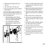
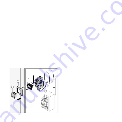
1. Create a standard height wall opening
for the flush box at the control unit in-
stallation site.
2. Route the connecting cables for the fans
from the wall opening to the flush box.
3. Route the top-hat rail power supply unit
cable from the junction box to the flush
box.
4. Mount the flush box in wall opening.
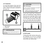
5. Connect the connecting cables for the
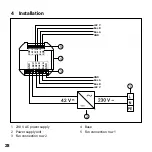
fans to the base (+42 V, bus A, bus B,
GND).
6. Connect the top-hat rail power supply
unit cable to the base (+42 V, GND)
7. Secure the base in the flush box.
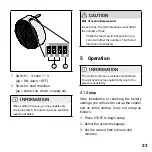
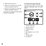
8. Insert the programming unit and frame
into the base.
9. Install the top-hat rail power supply unit
on the top-hat rail in the junction box.
10. Connect the mains cable to the power
supply unit.
8. Place the power supply unit in the
flush box.
9. Secure the base in the flush box.
10. Insert the programming unit and frame
into the base.
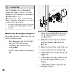
Top-hat rail power supply unit (option 2)
Route the following cables from the con-
trol unit installation site:
• Each data cable (e.g. LiYY (4x0.25
mm² to 0.75 mm²)) to each ventilation
unit in star or series configuration
• A 42 V cable (2x1.5 mm²) to the
top-hat rail power supply unit in the
junction box
42 V
1
2
3
42 V
5

