38
sensor per zone.
As soon as the sensor is detected, the LED
on the PCB flashes blue, and the automatic
mode and sensor information icons appear
in the control unit menu.
CAUTION
Risk of damage to electrical components!
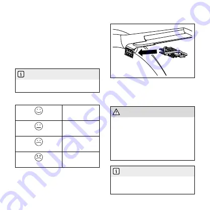
If you insert the sensor incorrectly, you may
damage the electrical components of the fan
and sensor.
• Insert the sensor PCB into the connection
with the soldered 2x4 pins facing downward
(see illustration).
INFORMATION
When automatic mode starts, the environ-
mental parameters are first measured for a
few minutes.
5.5 Filter replacement
The control unit determines when the filter
should be replaced, depending on the re-
quired air flow rate. As soon as a filter re-
quires replacement, the filter status icon in
the main screen flashes. In the filter status
menu, you can confirm filter replacement
and the interval will reset.
INFORMATION
The optimum time until filter replacement can vary
depending on local environmental influences.
Filter status
Contamination < 25 %
No action required.
Contamination < 50 %
Order a replacement
filter.
Contamination > 75 %
Check the filter in
good time; replace if
necessary.
Contamination = 100 %
Check the
filter; replace if
necessary.
5.6 Sensor unit
You can connect the optional sensor
directly to the fan. You can only use one

