32
CAUTION
Risk of fan damage!
Incorrect connector assignments can cause the
fan to malfunction, or damage it.
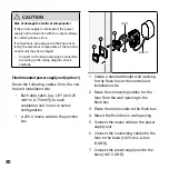
• Check the programming unit connection
and connector assignment carefully.
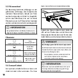
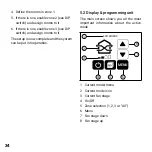
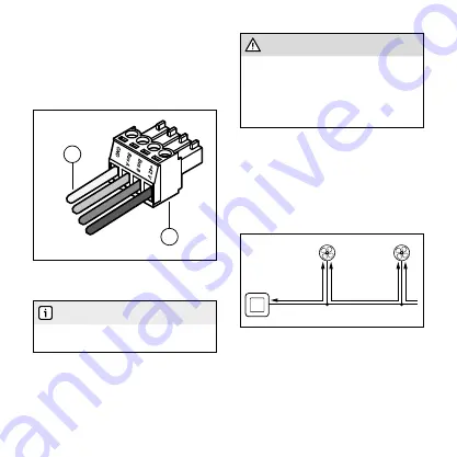
If you have several fans connected in
series, we recommend routing branches
from the main connecting cable to each
individual fan. Here, note segment length
LS of the cable cross-section used (chap-
ter 4.1). The cable must also be flexible.
Rigid cables must not be routed to the fan.
L
s
L
s
4.3 DIP switch
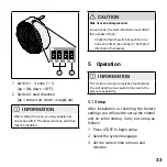
The fans have a DIP switch on the top. Dur-
ing installation, this must be configured
according to the design, so that the control
unit and fans can communicate.
4.2 Connection
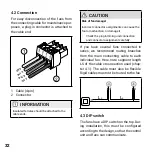
For easy disconnection of the fans from
the connecting cable for maintenance pur-
poses, a plug-in connector is attached to
the cable end.
GND
Bus A
Bus B
+42 V
2
1
1 Cable (4-pin)
2 Connector
INFORMATION
Insulated ferrules should be attached to the
cable ends.

