background image


44 


For work on the equipment you will need the 
following tools: 


Torque spanner (US: wrench) 4-40 Nm 


Torque spanner (US: wrench) 20-120 Nm 


2 Spanners A. F. 8 mm 


2 Spanners A. F. 19 mm (TK 23) or 24 mm (TK 
24) 


Screwdriver 6 mm 


Screwdriver 10 mm 


Exchanging the regulator unit of equipment 

with DN 50 


Remove the cover as described in section 
"

Removing cover of equipment with DN 50

from page  34 onwards. 


The regulator set comprises the whole regulator 
unit with the adjustment screw attached to it. 


Replace the regulator unit with the attached 
adjustment screw with a new one. 


Attach the cover to the body as described in 
section "

Mounting cover of equipment with DN 

50

" from page  38 onwards. 


Exchanging the regulator unit of equipment 

with DN 65 - 100 


Remove the cover as described in section 
"

Removing cover of equipment with DN 65 - 

100

" from page  36 onwards. 


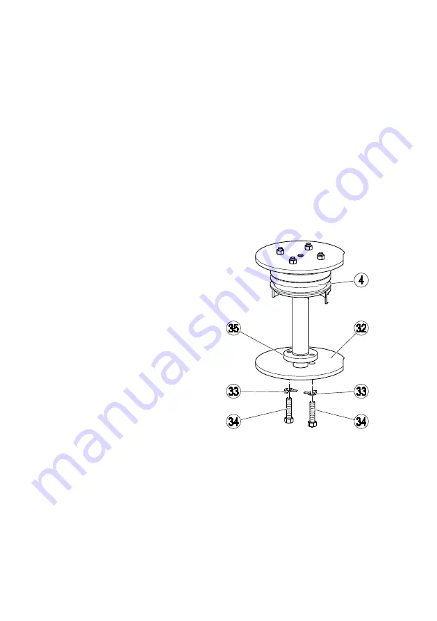
To take out the regulator unit (4) you have to 
remove the lift plate (32). 


Bend open the retaining metal straps (33). 


Remove the hexagon-head cap bolts (34). 


Detach the lift plate (32) from the regulator unit. 


Unscrew the washer nut (35) from the stem of 
the regulator unit. 


Lift the regulator unit (21) off the body. 


Put a new regulator unit into the body. 


Screw the washer nut (35) onto the stem of the 
regulator unit. 

The stop dog for the lift plate at the lower end of the 
stem must protrude approx. 3 to 4 mm after 
positioning the lift plate in place. 


Put the lift plate (32) onto the stem of the 
regulator unit. 


Turn the lift plate until the bores in the lift plate 
and in the washer nut are aligned one on top of 
the other. 


Put the retaining metal straps (33) onto the 
threads of the hexagon-head cap bolts. 


Screw the hexagon-head cap bolts (34) into the 
bores. 


Tighten the hexagon-head cap bolts with a 
torque of 5 Nm. 


Bend back the retaining metal straps. 


Attach the cover to the body as described in 
section "

Mounting cover of equipment with DN 

65 - 100

" from page  40  onwards. 


Содержание TK 23

Страница 1: ...Steam Trap for Large Condensate Flowrates TK 23 TK 24 Original Installation Instructions 819309 01 ...

Страница 2: ...11 Mounting and connecting the equipment 11 Preparing installation 11 Connecting the equipment 12 Adapting settings 13 Special adjustments for equipment with DN 50 14 Special adjustments for equipment with DN 65 24 Operation 34 After operation 34 Removing external dirt deposits 34 Maintaining the equipment 34 Servicing the equipment and installing spare parts 42 Troubleshooting 49 Putting the equi...

Страница 3: ...n operating manual is available to the operator The installation operating manual is part of the equipment Please hand over this installation operating manual when selling the equipment or passing it on Formatting features in the document Certain text elements of this installation operating manual feature a specific typographic design You can easily distinguish the following text elements Standard...

Страница 4: ...lecting suitable lifting gear and understanding the rules for its safe use Working with dangerous contaminated hot or pressurized fluids Risk of minor injuries Sharp edges on internals present the danger of cuts to hands Always wear industrial gloves when servicing the equipment If the support of the equipment during installation is insufficient the equipment might fall down thereby causing bruise...

Страница 5: ...ope of supply and equipment specification Scope of supply Our equipment is delivered packed and ready for assembly Equipment specification TK 23 and TK 24 are operationally identical but differ in their limiting conditions and materials of construction Equipment of type TK 23 is rated for nominal pressure PN16 TK 24 for nominal pressure PN 25 Equipment of various sizes differ in the following Equi...

Страница 6: ...on 1 Cap nut 2 Hexagon head cap bolts 4 pcs 3 Cover 4 Regulator unit 5 Body Item no Designation 6 Direction of flow arrow 7 Type specification on body instead of name plate 8 Thermostatic membrane regulator capsule 3 pcs 9 Adjustment screw 10 Sealing plug ...

Страница 7: ...per cover 3 Cover 2 pcs 4 Regulator unit 5 Body 6 Direction of flow arrow Item no Designation 7 Type specification on body instead of name plate 8 Thermostatic membrane regulator capsule 4 pcs 10 Sealing plug 2 pcs 11 Adjustment screw for maximum flowrate 12 Adjustment screw for minimum flowrate leak passage ...

Страница 8: ...te quarter year Application of European Directives Pressure Equipment Directive The equipment conforms to this directive see Manufacturer s Declaration section and can be used for the following media Fluids of group 2 ATEX Directive The equipment does not have its own potential ignition source and is not subject to this directive see Manufacturer s Declaration section When installed static electri...

Страница 9: ...ion The pressure in the chamber 18 drops below the upstream pressure and as a consequence the regulator unit is lifted and the valve 20 opens The condensate or the gas is discharged A small part of the fluid leak passage flows through the regulator unit with the membrane regulator capsules This partial flow enters the chamber through the annular slot 17 and flows through the regulator unit and the...

Страница 10: ...cone 19 This ensures that the membrane regulator capsules always have the same temperature as the fluid Immediately before the boiling temperature of water is reached the membrane regulator capsules are back in the closed position The annular slot causes the pressure in the chamber to drop and consequently the valve closes The dampening plate 22 and the chamber 23 prevent the steam trap from openi...

Страница 11: ...ing the equipment Please contact the manufacturer if you cannot comply with the recommended storage conditions Transporting the equipment Meet the requirements for storage also when transporting the equipment Prior to transport seal off connections with sealing plugs If you do not have the sealing plugs supplied with the equipment use appropriate seal caps to seal off the connections For short dis...

Страница 12: ... on the equipment body matches the direction of flow in the pipe Specialist personnel must be highly qualified and fully experienced in making pipe connections for the respective type of end connection Attention Equipment will be damaged if the end connections are undersized Make sure that the connections are strong and rigid enough to support the weight of the equipment and to withstand the force...

Страница 13: ...s is provided with two adjustment screws Use the adjustment screw on the top cover to regulate the maximum flowrate Use the adjustment screw on the bottom cover to regulate the minimum flowrate DANGER Personnel working on pipes are exposed to safety risks and may suffer severe injuries poisoning or even loss of life Make sure that no hot or hazardous fluid is in the equipment or the pipes Make sur...

Страница 14: ...sate as continuously as possible you have to reduce the maximum flowrate To do so you must limit the valve travel in the opening direction Attention Malfunctions due to banking up of condensate Limiting the maximum flowrate changes the factory set leak passage partial flow The equipment closes as soon as steam arrives Note that the responsiveness of the membrane regulator is reduced due to the lac...

Страница 15: ...is yields a ratio of 6 75 100 9 75 According to the lift restriction chart a ratio of 75 line A corresponds to one turn to the right of the adjustment screw Make sure that the equipment is depressurized cooled down to room temperature and free from fluid To reduce the pressure through the bore in the cover slowly loosen the sealing plug by two turns 10 Remove the cap nut 1 Remove the outer gasket ...

Страница 16: ...ent screw Put the hexagon nut 25 onto the adjustment screw 9 Make sure that the adjustment screw cannot rotate For this purpose you can for example push the tip of a screwdriver into the slot of the adjustment screw Tighten the hexagon nut 25 with a torque of 30 Nm Put the new outer gasket 26 onto the adjustment screw Screw the cap nut 1 onto the adjustment screw Tighten the cap nut with a torque ...

Страница 17: ... to this ratio The capacity charts are shown in section Capacity Charts on page 56 The lift restriction charts are shown in section Lift Restriction Charts from page 58 onwards Example The charts shown in this example are reduced in size Use the charts in original size to ascertain the required setting A minimum flowrate of 0 9 t h for hot fluid and a differential pressure of 0 85 bar is desired U...

Страница 18: ...ent screw Remove the hexagon nut 25 Remove the inner gasket 26 from the adjustment screw Screw in the adjustment screw 9 until it hits the stop Remove the sealing plug 10 Take the gasket 27 out of the body Insert a screwdriver through the bore for the sealing plug and push down the lift plate 21 Loosen the adjustment screw 9 until the lift plate starts to lift To change the minimum flowrate loosen...

Страница 19: ... a screwdriver into the slot of the adjustment screw Tighten the hexagon nut 25 with a torque of 30 Nm Put the new outer gasket 26 onto the adjustment screw Screw the cap nut 1 onto the adjustment screw Tighten the cap nut with a torque of 30 Nm Insert the new gasket 27 into the bore of the sealing plug Put the sealing plug 10 into the bore The torque for the sealing plug depends on the equipment ...

Страница 20: ...ne regulator is reduced due to the lack of a partial flow As a result condensate may bank up Make sure that the process in the higher level plant system is not impaired by banking up of condensate Make sure that the equipment is depressurized cooled down to room temperature and free from fluid To reduce the pressure through the bore in the cover slowly loosen the sealing plug by two turns 10 Remov...

Страница 21: ...5 onto the adjustment screw 9 Make sure that the adjustment screw cannot rotate For this purpose you can for example push the tip of a screwdriver into the slot of the adjustment screw Tighten the hexagon nut 25 with a torque of 30 Nm Put the new outer gasket 26 onto the adjustment screw Screw the cap nut 1 onto the adjustment screw Tighten the cap nut with a torque of 30 Nm Insert the new gasket ...

Страница 22: ...ug by two turns 10 Remove the cap nut 1 Remove the outer gasket 26 from the adjustment screw Remove the hexagon nut 25 Remove the inner gasket 26 from the adjustment screw Screw in the adjustment screw 9 until it hits the stop Remove the sealing plug 10 Take the gasket 27 out of the body Insert a screwdriver through the bore for the sealing plug and push down the lift plate 21 Loosen the adjustmen...

Страница 23: ... a screwdriver into the slot of the adjustment screw Tighten the hexagon nut 25 with a torque of 30 Nm Put the new outer gasket 26 onto the adjustment screw Screw the cap nut 1 onto the adjustment screw Tighten the cap nut with a torque of 30 Nm Insert the new gasket 27 into the bore of the sealing plug Put the sealing plug 10 into the bore The torque for the sealing plug depends on the equipment ...

Страница 24: ...f the equipment To ascertain the required number of turns of the adjustment screw proceed as follows Determine the ratio of the desired maximum flowrate to the flowrate set at our factory Refer to the lift restriction chart to ascertain the number of turns of the adjustment screw that corresponds to this ratio The capacity charts are shown in section Capacity Charts on page 56 The lift restriction...

Страница 25: ... the cover slowly loosen the sealing plug by two turns 10 Remove the cap nut 1 Remove the outer gasket 26 from the adjustment screw Remove the hexagon nut 25 Remove the inner gasket 26 from the adjustment screw Screw out the upper adjustment screw 11 until a resistance is felt Turn the upper adjustment screw 11 by the required number of turns ...

Страница 26: ...cified torque Insert the new gasket 27 into the bore of the upper sealing plug Put the sealing plug 10 into the bore The torque for the sealing plug depends on the equipment type TK 23 requires 20 Nm TK 24 requires 40 Nm Fasten the sealing plug with the specified torque Adjusting a minimum flowrate To adjust a minimum flowrate partial flow leak passage change the valve travel in the closing direct...

Страница 27: ...s a ratio of 6 5 100 31 21 According to the lift restriction chart a ratio of 21 line B corresponds to 2 turns to the right of the adjustment screw Make sure that the equipment is depressurized cooled down to room temperature and free from fluid To reduce the pressure through the bore in the cover slowly loosen the sealing plug by two turns 10 Remove the lower cap nut 1 Remove the outer gasket 26 ...

Страница 28: ...stment screw The torques required for tightening the hexagon nut 25 and the cap nut 1 depend on the equipment type TK 23 requires 20 Nm TK 24 requires 30 Nm Fasten the hexagon nut with the specified torque Put the new outer gasket 26 onto the lower adjustment screw Screw the cap nut 1 onto the adjustment screw Fasten the cap nut with the specified torque Put a new gasket 27 over the thread of the ...

Страница 29: ...sult condensate may bank up Make sure that the process in the higher level plant system is not impaired by banking up of condensate To ensure that the equipment gives steam tight shut off the following work must be performed on the lower adjustment screw Make sure that the equipment is depressurized cooled down to room temperature and free from fluid To reduce the pressure through the bore in the ...

Страница 30: ...stment screw The torques required for tightening the hexagon nut 25 and the cap nut 1 depend on the equipment type TK 23 requires 20 Nm TK 24 requires 30 Nm Fasten the hexagon nut with the specified torque Put the new outer gasket 26 onto the lower adjustment screw Screw the cap nut 1 onto the adjustment screw Fasten the cap nut with the specified torque Put a new gasket 27 over the thread of the ...

Страница 31: ...ower adjustment screw Remove the hexagon nut 25 Remove the inner gasket 26 from the lower adjustment screw Screw out the adjustment screw 12 until a resistance is felt Remove the upper sealing plug 10 Take the gasket 27 out of the bore for the sealing plug Insert a screwdriver through the bore for the upper sealing plug and push down the dampening plate 22 Keep pushing it down until the cone 19 re...

Страница 32: ...stment screw The torques required for tightening the hexagon nut 25 and the cap nut 1 depend on the equipment type TK 23 requires 20 Nm TK 24 requires 30 Nm Fasten the hexagon nut with the specified torque Put the new outer gasket 26 onto the lower adjustment screw Screw the cap nut 1 onto the adjustment screw Fasten the cap nut with the specified torque Put a new gasket 27 over the thread of the ...

Страница 33: ...at the adjustment screw cannot rotate For this purpose you can for example push the tip of a screwdriver into the slot of the adjustment screw The torques required for tightening the hexagon nut 25 and the cap nut 1 depend on the equipment type TK 23 requires 20 Nm TK 24 requires 30 Nm Fasten the hexagon nut with the specified torque Put a new outer gasket 26 onto the upper adjustment screw Screw ...

Страница 34: ...trol unit To remove dirt deposits rinse the equipment with fresh water and wipe it with a clean lint free cloth To remove any persistent residues use a cleaning agent that is suitable for the material and carefully wipe the equipment with a clean lint free cloth Remove any parts that are dirty and cannot be cleaned properly Removing cover of equipment with DN 50 DANGER Personnel working on pipes a...

Страница 35: ...ve the gasket 27 You can now remove the cover together with the attached adjustment screw 9 and the regulator unit from the body Attention A deformed sleeve can cause malfunctions When removing the cover take care that the sleeve does not fall out of the body Take the cover 3 together with the regulator unit 4 out of the body Remove the body gasket 31 Make sure that the sleeve 30 cannot fall out o...

Страница 36: ...ff and protected against unauthorised or unintended activation Make sure that the equipment and the pipes have cooled down to room temperatures Wear protective clothing that is suitable for the fluid and if necessary wear protective gear For more information on suitable protective clothing and safety gear refer to the safety data sheet of the fluid in question Make sure that the equipment is depre...

Страница 37: ...dy Remove the body gasket 31 Make sure that the sleeve 30 cannot fall out of the body Unscrew the adjustment screw 11 or 12 from the cover To remove the second cover repeat these steps The regulator unit 4 is now accessible To remove the regulator unit proceed as describe in section Exchanging the regulator unit of equipment with DN 65 100 from page 44 onwards ...

Страница 38: ...lace defective membrane regulator capsule with a new one Mounting cover of equipment with DN 50 Attention Equipment may leak if the gasket is damaged It is therefore essential that you always insert a new gasket before re attaching the cover Make sure that the cover is not tilted or skewed when refitted Clean the gasket surfaces of the cover and body Apply a light smear of lubricant to the threads...

Страница 39: ...r this purpose you can for example push the tip of a screwdriver into the slot of the adjustment screw Tighten the hexagon nut 25 with a torque of 30 Nm Put the new outer gasket 26 onto the adjustment screw Screw the cap nut 1 onto the adjustment screw Tighten the cap nut with a torque of 30 Nm Insert the new gasket 27 into the bore of the sealing plug Put the sealing plug 10 into the bore The tor...

Страница 40: ...the bolt heads The lubricant must have the same properties as OKS 217 Mount the two covers one after the other The following section describes how to mount the upper cover with the adjustment screw 11 Mount the lower cover with the adjustment screw 12 in the same way The following drawings show the components of both covers Put a new body gasket 31 onto the sleeve 30 Screw the adjustment screw 11 ...

Страница 41: ... torque for the hexagon nut 25 depends on the equipment type Equipment of type TK 23 requires a torque of 20 Nm Equipment of type TK 24 requires a torque of 30 Nm Fasten the hexagon nut with the specified torque Put the new outer gasket 26 onto the adjustment screw Screw the cap nut 1 onto the adjustment screw The torque for the cap nut depends on the equipment type Equipment of type TK 23 require...

Страница 42: ...ds Servicing the equipment and installing spare parts You may exchange the following component parts in case of wear or damage Spare Parts Item no Designation Stock code DN50 DN65 80 DN100 26 27 31 42 Gasket set 1 Body gasket 31 1 Gasket for regulator unit 42 4 Gaskets 26 27 377364 26 27 31 Gasket set 1 Body gasket 31 7 Gaskets 26 27 377365 377366 ...

Страница 43: ...et 31 7 Gaskets 26 27 377235 377236 8 26 27 31 Capsule set 5H2 3 Membrane regulator capsules 5H2 8 1 Body gasket 31 4 Gaskets 26 27 377237 8 26 27 31 Capsule set 5H2 4 Membrane regulator capsules 5H2 8 2 Body gasket 31 7 Gaskets 26 27 377238 377239 4 26 27 31 Regulator set 1 Regulator unit 5H2 4 1 Body gasket 31 3 Gaskets 26 27 379914 4 26 27 31 Regulator set 1 Regulator unit 5H2 4 2 Body gasket 3...

Страница 44: ...e out the regulator unit 4 you have to remove the lift plate 32 Bend open the retaining metal straps 33 Remove the hexagon head cap bolts 34 Detach the lift plate 32 from the regulator unit Unscrew the washer nut 35 from the stem of the regulator unit Lift the regulator unit 21 off the body Put a new regulator unit into the body Screw the washer nut 35 onto the stem of the regulator unit The stop ...

Страница 45: ...n question Remove the cover as described in section Removing cover of equipment with DN 50 from page 34 onwards Remove the hexagon nuts 43 and the hexagon head cap bolts 39 You can now disassemble the regulator unit Take the adjustment screw 9 out of the regulator unit Remove the guide plate 40 Remove the sleeve 41 and the gasket 42 from the cone 19 Detach the capsule support 36 from the regulator...

Страница 46: ... safety risks and may suffer severe injuries poisoning or even loss of life Make sure that no hot or hazardous fluid is in the equipment or the pipes Make sure that the pipes upstream and downstream of the equipment are depressurised Make sure that the installation is switched off and protected against unauthorised or unintended activation Make sure that the equipment and the pipes have cooled dow...

Страница 47: ...e exposed to safety risks and may suffer severe injuries poisoning or even loss of life Make sure that no hot or hazardous fluid is in the equipment or the pipes Make sure that the pipes upstream and downstream of the equipment are depressurised Make sure that the installation is switched off and protected against unauthorised or unintended activation Make sure that the equipment and the pipes hav...

Страница 48: ...ce the body gasket 31 with a new one The mounting method for the cover depends on the equipment type How to mount the cover of equipment with DN50 is described on page 38 How to mount the cover of equipment with DN 65 100 is described on page 40 Attach cover to the equipment as described in the respective section ...

Страница 49: ...es The membrane regulator capsules are worn The seat is leaking Replace the membrane regulator capsules with new ones The bypass is open Close the bypass Insufficient condensate discharge Insufficient thermal output of the user The shut off valves for condensate inlet or outlet are closed Open the shut off valves The condensate inlet or outlet is dirt clogged Clean the pipes Clean the equipment Re...

Страница 50: ...n point towards the steam trap The condensate is lifted upstream of the steam trap Lay the condensate line with a gradient so that the condensate is free to fall towards the steam trap Change the orientation of the condensate line The steam trap is adjusted to give steam tight shut off Restore the factory setting If necessary re adjust the settings of the steam trap The condensate temperature is h...

Страница 51: ...l that is suitable for the fluid used The equipment has been damaged by frost Replace the equipment with a new one When shutting down the installation make sure that the condensate lines and the steam trap are completely drained The equipment has been damaged by waterhammer Replace the equipment with a new one Take appropriate measures to protect the equipment against waterhammer e g by installing...

Страница 52: ...mental damage may be caused by poisonous fluid residues Before disposing of the equipment make sure that it is clean and free of fluid residues For the disposal of all materials observe the pertinent legal regulations concerning waste disposal Remove all residues from the equipment For the disposal of all residues observe the pertinent legal regulations concerning waste disposal Removing the equip...

Страница 53: ...and leak free Use the equipment only for its intended purpose and the service conditions for which it was specified Disposing of the equipment Caution Environmental damage may be caused by poisonous fluid residues Before disposing of the equipment make sure that it is clean and free of fluid residues For the disposal of all materials observe the pertinent legal regulations concerning waste disposa...

Страница 54: ...00 inch 2 2 3 4 2 2 3 4 Dimensions mm L 230 290 310 350 230 290 310 350 H 204 175 175 175 204 180 180 180 H1 175 175 188 170 170 188 H2 350 350 363 350 350 368 D 165 185 200 220 165 185 200 235 S1 approx 50 approx 200 approx 50 approx 200 Weight kg 16 25 27 43 17 28 31 56 1 Withdrawal distance ...

Страница 55: ...gulator capsule 0H2 Membrane regulator capsule 5H2 Membrane regulator capsule 0H2 Membrane regulator capsule 5H2 PMO admissible operating pressure barg 131 211 TMO admissible inlet temperature ts 2 PMX admissible differential pressure 5 1 10 5 1 14 1 If the membrane regulator capsule type 0H2 is used the max admissible service pressure is 5 barg 2 Saturated steam temperature Do not exceed max admi...

Страница 56: ...56 Capacity Charts Capacity chart for hot water A Flowrate B Differential pressure Δ PMX ...

Страница 57: ...57 Capacity chart for cold water A Flowrate B Differential pressure Δ PMX ...

Страница 58: ...Lift restriction chart DN 50 A Example of maximum capacity B Example of minimum flowrate leak passage C Max capacity in of max possible flowrate D Turns to the left E Min capacity in of max possible flowrate F Turns to the right ...

Страница 59: ...ity B Example of minimum flowrate leak passage C Max capacity in of max possible flowrate D Turns to the right for lower adjustment screw minimum flowrate E Min capacity in of max possible flowrate F Turns to the right for upper adjustment screw maximum flowrate ...

Страница 60: ...striction chart DN 100 A Max capacity in of max possible flowrate B Turns for lower adjustment screw minimum flowrate C Min capacity in of max possible flowrate D Turns for upper adjustment screw maximum flowrate ...

Страница 61: ...turer To download the current Declaration of Conformity or Declaration by Manufacturer go to www gestra com documents or contact GESTRA AG Münchener Straße 77 28215 Bremen Germany Telefon 49 421 3503 0 Telefax 49 421 3503 393 E Mail info de gestra com Web www gestra de This declaration is no longer valid if modifications are made to the equipment without consultation with us ...

Страница 62: ...62 ...

Страница 63: ...63 ...

Страница 64: ...rld www gestra de GESTRA AG Münchener Straße 77 28215 Bremen Germany Telefon 49 421 3503 0 Telefax 49 421 3503 393 E Mail info de gestra com Web www gestra de 819309 01 07 2017 kx_mm 803358 03 GESTRA AG Bremen Printed in Germany ...

Отзывы: