90
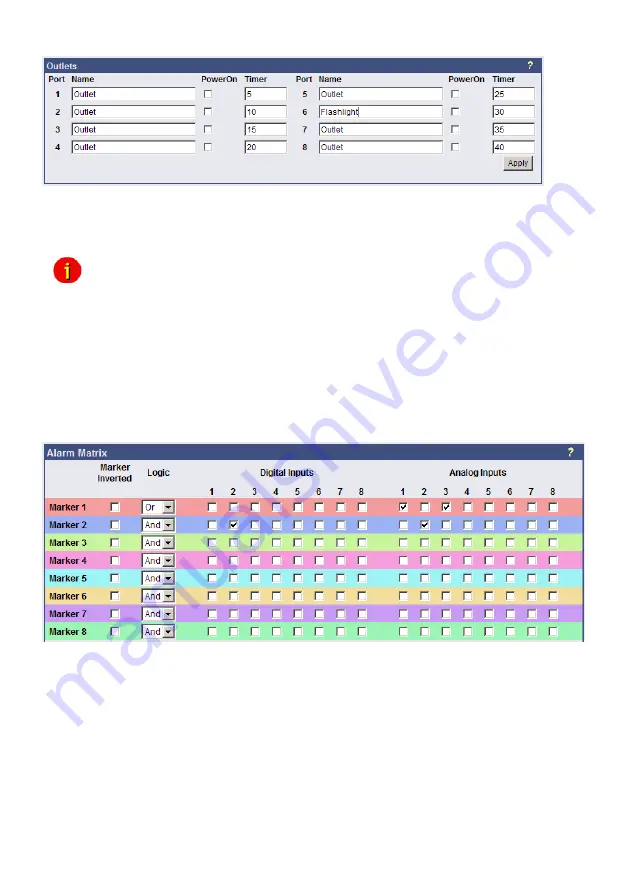
Figure 109:
SENSORMANAGER II Configuration Outlets
Furthermore it is possible to attach a timer value to each Outlet. This determinates how long
an outlet will be switched (in seconds). Set the
timer value to “0” if the outlet is to be switched
without any time limit.
Note: If you do not want to use a name for the Analog-, Digital Inputs or rather the
Outlets, please set the following into the single name area:
7.3.5
Alarm Matrix of the SENSORMANAGER II
The following “Alarm Matrix” gives you numerous possibilities to configure dependencies
between different alarm states and to logically combine them to different Event. This makes it
possible to process an alarm scenario in dependency of the status of several input sensors.
(For example: An alarm scenario is to be released only if two temperature sensors are out of
range or if the air condition is not active.
This requires to create a new event which gets “true”
only if 2 or more other events are true)
Figure 110:
Alarm matrix
– Marker configuration
In the figure above is shown the alarm matrix with its 8 markers to be set or unset. Each
marker thereby is a new state on which specific alarm scenarios can be released.
For example: In the figure above is configured that the Marker1 will be set, when at the
analogue
input 1 or 3 an alarm occurs. (Enabling the field “Marker Inverted” causes that
Marker1 will be unset in case of an alarm at analogue input 1 or 3.) Furthermore marker 2 will
be set, when at the digital input 2 and at the analogue input 2 an alarm state occurs at the
same time. (Means that an alarm at just one input is not sufficient for setting marker 2)
Accordingly it is possible to set (or unset) each marker in dependency of different digital and/or
analogue input states.
After having defined the conditions when markers are to be set resp. unset, you can specify
the actions to be executed when a marker will be set/unset. Therefore you have two
possibilities: The first is to handle the actions through the event configuration, described later
Содержание CS121BL
Страница 2: ......
Страница 68: ...66 Figure 72 HTTP Status Page Socomec Transfer Switch Figure 73 HTTP Status Page Eaton Transfer Switch ...
Страница 71: ...69 Figure 76 CS121 FTP Access Figure 77 CS121 FTP Context Menu Figure 78 CS121 FTP Folders ...
Страница 107: ...105 Figure 135 Internet Explorer LAN Proxy Einstellungen ...


