


GE M
EDICAL
S
YSTEMS
D
IRECTION
2300164-100, R
EVISION
7
V
IVID
™ 3 P
RO
/V
IVID
™ 3 S
ERVICE
M
ANUAL
Chapter 5 - Components and Function (Theory)
5-47
5-7-4
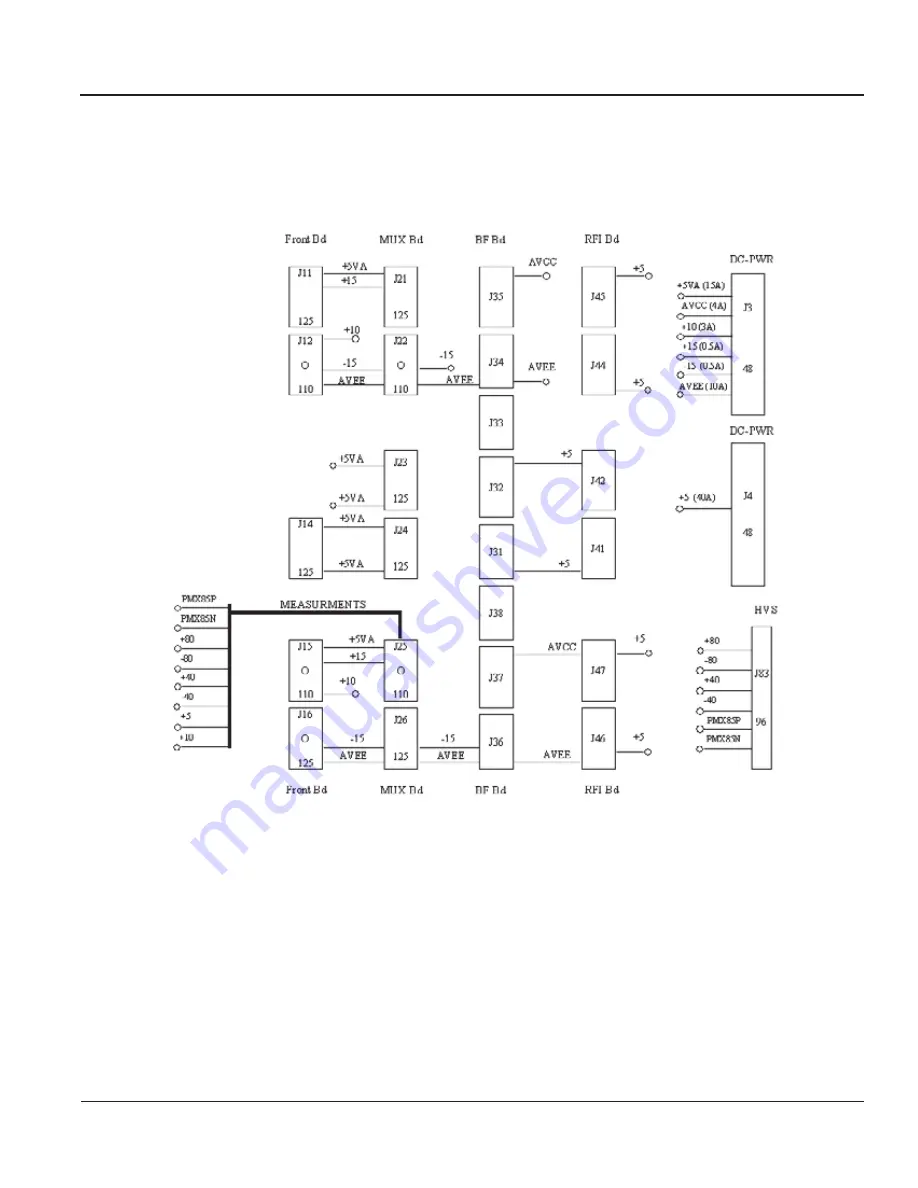
Front End DC Power Distribution
Figure 5-32 DC Distribution: Front End Crate (Vivid™ 4 Systems with RFI Configuration)
Artisan Technology Group - Quality Instrumentation ... Guaranteed | (888) 88-SOURCE | www.artisantg.com


