5-170
T35 TRANSFORMER PROTECTION SYSTEM – INSTRUCTION MANUAL
SYSTEM SETUP
CHAPTER 5: SETTINGS
5
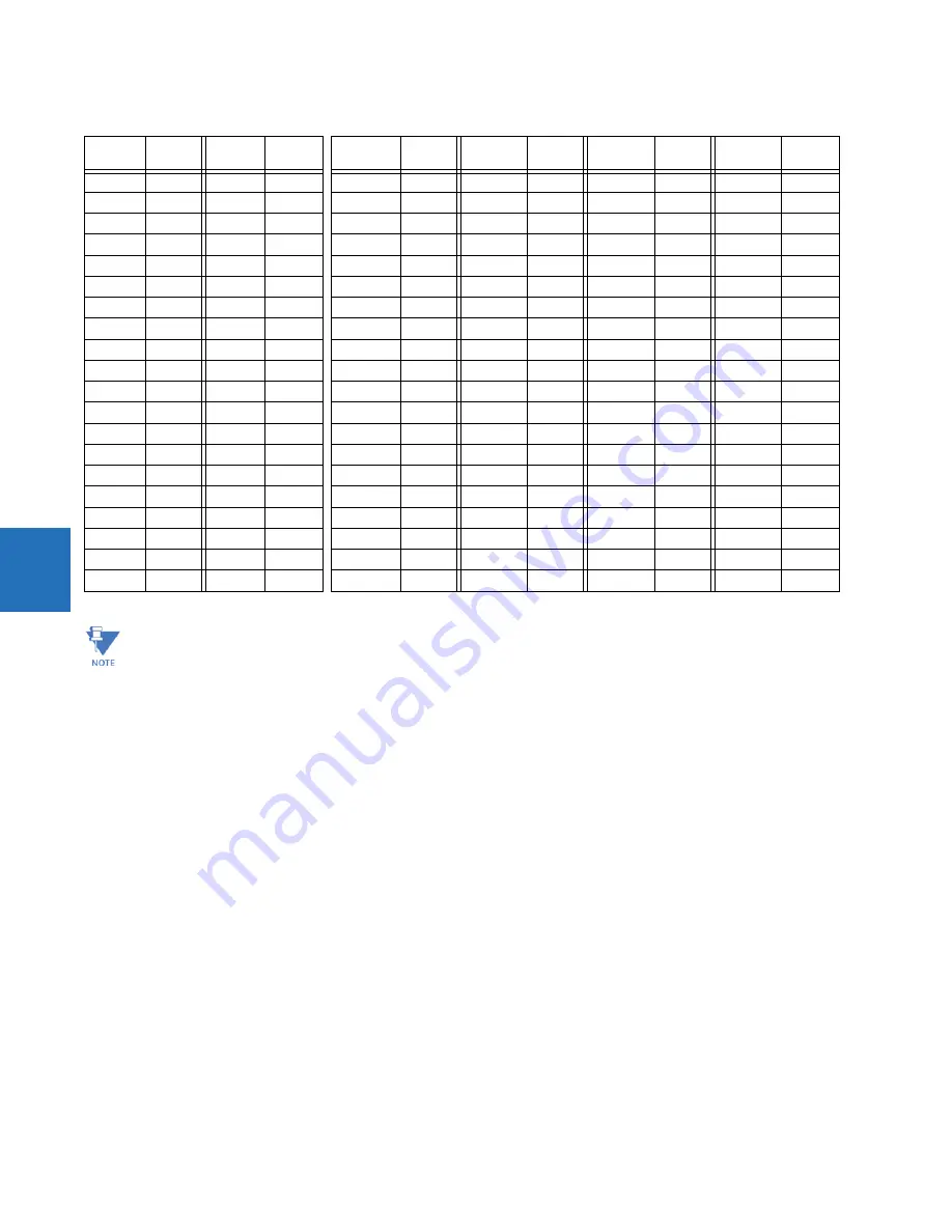
Table 5-20: FlexCurve table
5.5.7.2 FlexCurve configuration with EnerVista software
The EnerVista software allows for easy configuration and management of FlexCurves and their associated data points.
Prospective FlexCurves can be configured from a selection of standard curves to provide the best approximate fit, then
specific data points can be edited afterwards. Alternately, curve data can be imported from a specified file (.csv format) by
selecting the EnerVista
Import Data From
setting (
Settings > System Setup > FlexCurves > FlexCurve
).
Curves and data can be exported, viewed, and cleared by clicking the appropriate buttons. FlexCurves are customized by
editing the operating time (ms) values at pre-defined per-unit current multiples. Note that the pickup multiples start at zero
(implying the "reset time"), operating time below pickup, and operating time above pickup.
5.5.7.3 Recloser curve editing
Recloser curve selection is special in that recloser curves can be shaped into a composite curve with a minimum response
time and a fixed time above a specified pickup multiples. There are 41 recloser curve types supported. These definite
operating times are useful to coordinate operating times, typically at higher currents and where upstream and
downstream protective devices have different operating characteristics. The recloser curve configuration window shown
here appears when the
Initialize From
setting in the EnerVista software is set to “Recloser Curve” and the
Initialize
FlexCurve
button is clicked.
Reset
Time
ms
Reset
Time
ms
Operate
Time
ms
Operate
Time
ms
Operate
Time
ms
Operate
Time
ms
0.00
0.68
1.03
2.9
4.9
10.5
0.05
0.70
1.05
3.0
5.0
11.0
0.10
0.72
1.1
3.1
5.1
11.5
0.15
0.74
1.2
3.2
5.2
12.0
0.20
0.76
1.3
3.3
5.3
12.5
0.25
0.78
1.4
3.4
5.4
13.0
0.30
0.80
1.5
3.5
5.5
13.5
0.35
0.82
1.6
3.6
5.6
14.0
0.40
0.84
1.7
3.7
5.7
14.5
0.45
0.86
1.8
3.8
5.8
15.0
0.48
0.88
1.9
3.9
5.9
15.5
0.50
0.90
2.0
4.0
6.0
16.0
0.52
0.91
2.1
4.1
6.5
16.5
0.54
0.92
2.2
4.2
7.0
17.0
0.56
0.93
2.3
4.3
7.5
17.5
0.58
0.94
2.4
4.4
8.0
18.0
0.60
0.95
2.5
4.5
8.5
18.5
0.62
0.96
2.6
4.6
9.0
19.0
0.64
0.97
2.7
4.7
9.5
19.5
0.66
0.98
2.8
4.8
10.0
20.0
The relay using a given FlexCurve applies linear approximation for times between the user-entered points. Take
care when setting the two points that are close to the multiple of pickup of 1; that is, 0.98 pu and 1.03 pu. It is
recommended to set the two times to a similar value, otherwise the linear approximation can result in undesired
behavior for the operating quantity that is close to 1.00 pu.
Содержание T35
Страница 9: ...TABLE OF CONTENTS T35 TRANSFORMER PROTECTION SYSTEM INSTRUCTION MANUAL ix ABBREVIATIONS INDEX ...
Страница 10: ...x T35 TRANSFORMER PROTECTION SYSTEM INSTRUCTION MANUAL TABLE OF CONTENTS ...
Страница 14: ...1 4 T35 TRANSFORMER PROTECTION SYSTEM INSTRUCTION MANUAL FOR FURTHER ASSISTANCE CHAPTER 1 INTRODUCTION 1 ...
Страница 202: ...4 88 T35 TRANSFORMER PROTECTION SYSTEM INSTRUCTION MANUAL FLEXLOGIC DESIGN USING ENGINEER CHAPTER 4 INTERFACES 4 ...
Страница 472: ...5 270 T35 TRANSFORMER PROTECTION SYSTEM INSTRUCTION MANUAL TESTING CHAPTER 5 SETTINGS 5 ...
Страница 500: ...6 28 T35 TRANSFORMER PROTECTION SYSTEM INSTRUCTION MANUAL PRODUCT INFORMATION CHAPTER 6 ACTUAL VALUES 6 ...
Страница 514: ...7 14 T35 TRANSFORMER PROTECTION SYSTEM INSTRUCTION MANUAL TARGETS MENU CHAPTER 7 COMMANDS AND TARGETS 7 ...
Страница 580: ...A 16 T35 TRANSFORMER PROTECTION SYSTEM INSTRUCTION MANUAL FLEXANALOG ITEMS APPENDIX A FLEXANALOG OPERANDS A ...
Страница 588: ...C 6 T35 TRANSFORMER PROTECTION SYSTEM INSTRUCTION MANUAL COMMAND LINE INTERFACE APPENDIX C COMMAND LINE INTERFACE C ...
Страница 596: ...iv T35 TRANSFORMER PROTECTION SYSTEM INSTRUCTION MANUAL ABBREVIATIONS ...


