GE T17 Скачать руководство пользователя страница 47

Model T17 Installation Guide

39

Chapter 2. Installing the Pipe Nozzles

2.4.2 Selecting and Marking the First Nozzle Location - MR2 Mid-Radius (cont.)

To mark the first nozzle location, complete the following steps:

1.

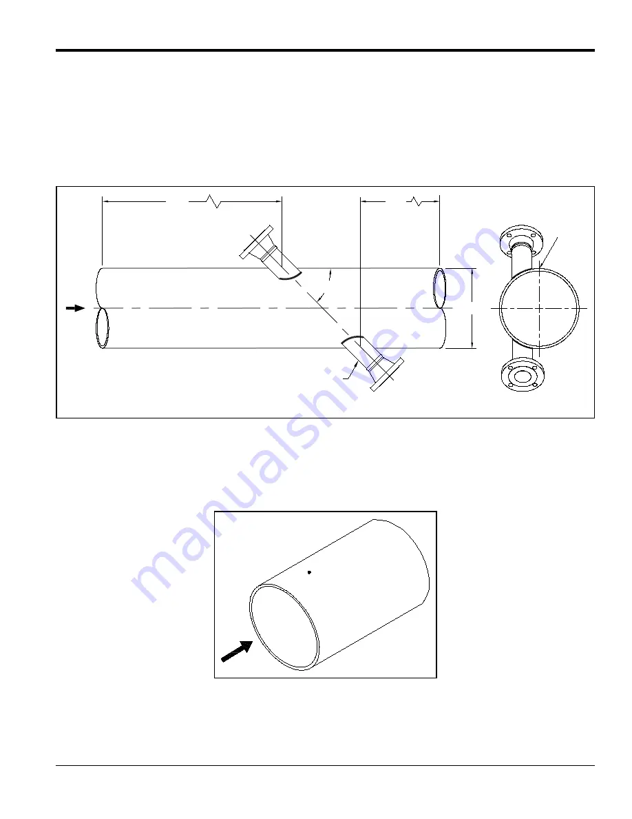
For optimum performance, you should select a location that has at least 20 pipe diameters of straight, 
undisturbed flow upstream and 10 pipe diameters of straight, undisturbed flow downstream from the 
measurement point (see 

Figure 48

 below). Undisturbed flow means avoiding sources of turbulence such as 

valves, flanges, elbows, swirl and disturbed flow profiles.

Figure 48: MR2 Mid-Radius Nozzle Locations

Note:

We recommend that you install the nozzles on a chord as near as possible to the horizontal plane for horizontal 
pipe. If you cannot find a proper nozzle location, please contact GE for assistance.

2.

Locate the top of the pipe and put a center punch mark there as a reference mark.

Figure 49: Punch Mark on Top of Pipe

FLOW

NOZZLE

(2 PLACES)

10D

20D

D

45°

TOP VIEW

END VIEW

TOP

Содержание T17

Страница 1: ...GE Oil Gas Flow 916 128 Rev D September 2020 Model T17 Ultrasonic Flow Transducer Installation Guide ...

Страница 2: ......

Страница 3: ...one or more registered trademark of Baker Hughes Company and its subsidiaries in one or more countries All third party product and company names are trademarks of their respective holders GE Oil Gas Model T17 Ultrasonic Flow Transducer Installation Guide 916 128 Rev D September 2020 ...

Страница 4: ...ii no content intended for this page ...

Страница 5: ...cting and Marking the First Nozzle Location MR1 Mid Radius 20 2 3 3 Determining and Marking the Second Nozzle Location MR1 Mid Radius 24 2 3 4 Installing the First Welding Boss MR1 Mid Radius 29 2 3 5 Installing the First Nozzle MR1 Mid Radius 32 2 3 6 Installing the Second Welding Boss and Nozzle MR1 Mid Radius 34 2 3 7 Hot Tapping the Pipe MR1 Mid Radius 35 2 3 8 Cold Tapping the Pipe MR1 Mid Ra...

Страница 6: ...ing for Installation 57 4 2 2 Mounting the Insertion Mechanism 58 4 2 3 Aligning the Downstream Transducer for Extended Range Installations 65 4 3 Connecting an XAMP 69 Chapter 5 Maintaining the T17 Transducers 5 1 Removing Transducers 75 5 2 Using the Insertion Mechanism 75 Chapter 6 Specifications 6 1 T17 Transducer Physical Specifications 79 6 2 T17 Transducer Certifications 79 ...

Страница 7: ...followed carefully WARNING This symbol indicates a risk of potential serious personal injury unless these instructions are followed carefully WARNING It is the responsibility of the user to make sure all local county state and national codes regulations rules and laws related to safety and safe operating conditions are met for each installation WARNING For installations in potentially hazardous ar...

Страница 8: ...ve 2012 19 EU The equipment that you bought has required the extraction and use of natural resources for its production It may contain hazardous substances that could impact health and the environment In order to avoid the dissemination of those substances in our environment and to diminish the pressure on the natural resources we encourage you to use the appropriate take back systems Those system...

Страница 9: ...on on pipes ranging from 4 to 12 in 100 to 300 mm or for using the BIAS 90 configuration please see the GE 916 117 Installation Guide 1 2 Transducer Construction Each T17 transducer assembly see Figure 1 below consists of the following components A fully sealed welded all metal body made from grade 2 titanium as standard A transducer head that consists of piezoelectric elements wired to the BNC co...

Страница 10: ...ational Metal Engineering PTE Limited IME Type 8080 8075 8066 or 7080 certified under SIRA 07ATEX1331U and IECEx SIR 07 0111U or equivalent that complies with EN 60079 0 2012 IEC 60079 0 2011 and EN 60079 1 2007 IEC 60079 1 2007 For example Cortem SL 26 1N certified under CESI 03ATEX032U or equivalent A certified metric to NPT adapter material brass may be used in addition to the compression fitti...

Страница 11: ...e flow range options Standard flow range operation of 0 1 to 328 f s 0 03 to 100 m s This configuration uses two 180 head T17 transducers Extended flow range operation of 0 1 to 394 f s 0 03 to 120 m s This configuration uses one 180 head T17 transducer and one 174 head T17 transducer Either of the above flow range options may be used in one of three possible signal path configurations Figure 2 be...

Страница 12: ...The Diametrical path nozzle installation procedure includes the following steps 1 Identifying the Nozzle Installation Kit Components Diametrical on page 5 2 Selecting and Marking the First Nozzle Location Diametrical on page 6 3 Determining and Marking the Second Nozzle Location Diametrical on page 8 4 Installing the First Welding Boss Diametrical on page 12 5 Installing the First Nozzle Diametric...

Страница 13: ...hey are the correct parts for your installation The Nozzle Installation Kit should contain the following items 2 Nozzles if purchased 2 Welding Bosses 1 Jig 1 Threaded Rod 1 in diameter with Washer and Nut IMPORTANT You will need to supply eight 5 8 studs with two nuts each for 3 x 150 flanges or eight 3 4 studs with two nuts each for 3 x 300 flanges Use Figure 4 below to help identify each compon...

Страница 14: ...zzle alignment is critical to the accurate operation of the Flowmeter Therefore all marking positioning and welding operations must be carried out with the utmost attention to accuracy The centerline of each nozzle must form an angle of 45 1 with the centerline of the pipe The centerlines of the two nozzles must form an angle of 180 1 with each other and the points where the two nozzle centerlines...

Страница 15: ...disturbed flow means avoiding sources of turbulence such as valves flanges elbows swirl and disturbed flow profiles Figure 6 Diametrical Nozzle Locations 2 We recommend that you install the nozzles on a diameter as near as possible to the horizontal plane i e 3 o clock and 9 o clock positions for a horizontal pipe Note If you cannot find a proper location please consult with GE Flow Application en...

Страница 16: ...econd nozzle location complete the following steps 1 The location for the second nozzle is typically a distance equal to one pipe outside diameter along the pipe from the first nozzle location and on the opposite side of the pipe i e 180 around Spray this area with a marking dye product Note For angles other than 45 the distance is equal to the pipe OD times the tangent of the installation angle 2...

Страница 17: ...e average outside diameter calculated in Step 2 on the previous page Length equal to 4 times the average outside diameter of the pipe Figure 10 Polyester Film Dimensions 4 Wrap the strip of film around the pipe with one edge running along the vertical scribe line at the first nozzle location Make sure the strip overlaps squarely around the pipe and mark the overlap position of the strip as shown i...

Страница 18: ... when the film is reapplied to the pipe Figure 12 Folding the Film 6 Mark the outside of the fold for reference as shown in Figure 13 below Figure 13 Marking the Film 7 Place the strip of film back on the pipe This time line up the overlap mark with the horizontal and vertical scribe lines see Figure 14 below Again make sure you wrap the strip of film squarely around the pipe Figure 14 Placing the...

Страница 19: ...tersection of the fold line and the second edge of the strip of film see Figure 15 below Center punch this location prior to removing the film Figure 15 Center Punch the Second Nozzle Location 9 Remove the film from the pipe 10 Scribe 6 long vertical and horizontal lines that intersect at the center punch mark see Figure 16 below Figure 16 Making Scribe Lines Fold Mark Side View Punch Here Second ...

Страница 20: ...e outside diameter d welding boss outside diameter 1 660 in Using the above equation values of X for some common pipe sizes were calculated and are listed in Table 1 below 2 Scribe the oblique center line on your pipe at the calculated distance from the true center line for your pipe size The oblique center line should be marked on the side of the true center line that is closer to the second nozz...

Страница 21: ...n in Figure 18 below Figure 18 Welding Boss Orientation 4 Clamp the welding boss in place using a pipe strap or equivalent so that it cannot move during tack welding 5 Check the boss alignment then tack weld the carbon steel welding boss to the pipe in each of the four grooves between the welding boss scribe marks 6 Remove the clamp and check the welding boss alignment again If the welding boss is...

Страница 22: ...ove the washer and nut from the threaded rod Figure 19 Inserting the Threaded Rod 2 Slide the nozzle over the threaded rod and align the contoured end of the nozzle so it matches the pipe arc Then slide the jig over the threaded rod fitting the jig into the welding boss see Figure 20 below Figure 20 Inserting the Nozzle and Jig CAUTION It is essential that the nozzle be set up and fixed in positio...

Страница 23: ... way around the nozzle must be removed and ground appropriately to provide the required clearance If the root gap is larger than the 0 094 in 2 4 mm dimension then suitably sized washers may be inserted between the jig and the nozzle on the four studs to reduce the root gap dimension 6 Tack weld the nozzle to the pipe at four diametrically opposed points with each tack being approximately 0 6 in 1...

Страница 24: ...he marked position see Figure 22 below as described in Installing the First Welding Boss Diametrical on page 12 and Installing the First Nozzle Diametrical on page 14 Figure 22 Installing the Second Welding Boss and Nozzle The completed installation should appear as shown in Figure 23 below Figure 23 Completed Diametrical Installation 45 FLOW WELDING BOSS NOZZLE 2 PLACES 2 PLACES ...

Страница 25: ...drill bit Then use a coupon retaining hole saw to cut a hole with a diameter of 2 50 in 63 5 mm minimum 2 2 8 Cold Tapping the Pipe Diametrical The procedure for cold tapping a pipe is the same as the hot tapping procedure However an isolation valve is not necessary during the process The hot tapping medium can be applied directly to the nozzle Isolation valves will be added after the tapping is c...

Страница 26: ...Mid Radius on page 20 3 Determining and Marking the Second Nozzle Location MR1 Mid Radius on page 24 4 Installing the First Welding Boss MR1 Mid Radius on page 29 5 Installing the First Nozzle MR1 Mid Radius on page 32 6 Installing the Second Welding Boss and Nozzle MR1 Mid Radius on page 34 7 Proceed to one of the following Hot Tapping the Pipe MR1 Mid Radius on page 35 Cold Tapping the Pipe MR1 ...

Страница 27: ... flanges or 3 x 150 flanges or eight 3 4 studs with two nuts each for 3 x 300 flanges Use Figure 25 below to help identify each component Figure 25 Components in Nozzle Installation Kit Depending on your configuration a pair of one of the nozzles listed in Table 2 below is included in your kit Table 2 Available Nozzles for MR1 Installations Construction Type ANSI Flange Rating Material Part Number...

Страница 28: ...osses CAUTION Correct nozzle alignment is critical to the accurate operation of the flow meter Therefore all marking positioning and welding operations must be carried out with the utmost attention to accuracy The centerline of each nozzle must form an angle of 45 1 with the centerline of the pipe The centerlines of the two nozzles must form an angle of 180 1 with each other and the points where t...

Страница 29: ...ownstream from the measurement point see Figure 27 below Undisturbed flow means avoiding sources of turbulence such as valves flanges elbows swirl and disturbed flow profiles Figure 27 MR1 Mid Radius Nozzle Locations Note We recommend that you install the nozzles on a chord as near as possible to the horizontal plane for horizontal pipe If you cannot find a proper nozzle location please contact GE...

Страница 30: ...e 23 for tabulated AS 2 values calculated from the above equation for common pipe sizes Note To clarify the use of the above equations see the bottom of page 26 for a typical example calculation Figure 29 Locating the MR1 Nozzles on the Pipe Y0 D 2W 2 Chord Location where Chord Location 1 2 for mid radius installations X0 D 2 2 Y0 2 AS 2 D 2 β where β radian X0 Y0 atan S 2 Xo AS 2 D 2 B D 2W 2 D 2...

Страница 31: ... Location Table 3 AS 2 Values for Common Pipe Sizes with 0 375 Wall Thickness Pipe OD AS 2 Dimension inches mm inches mm 26 650 13 829 351 26 28 700 14 876 377 86 30 750 15 924 404 46 32 800 16 971 431 06 34 N A 18 018 N A 36 900 19 065 484 26 38 N A 20 113 N A 40 1000 21 160 537 46 42 1050 22 207 564 06 44 1100 23 254 590 66 46 N A 24 301 N A 48 1200 25 349 643 86 52 1300 27 443 697 06 54 N A 28 ...

Страница 32: ...nce equal to S along the pipe and located on the other side of the pipe For installation other than 45 the distance is equal to S times the tangent of the installation angle Steps 2 to 7 on the following pages are for the second nozzle located at 45 from the first nozzle Figure 32 Calculating the Second Nozzle Location IMPORTANT As shown above while looking down onto the header pipe with the flow ...

Страница 33: ...e calculations consider an MR1 installation for a STD Schedule 48 pipe a From standard pipe tables pipe OD 48 000 in and pipe wall thickness W 0 375 in b From the 1st equation Y0 48 000 2 x 0 375 2 x 0 5 11 813 in c From the 2nd equation Width S 2 x SQRT 48 2 2 11 81 2 41 783 in d From the 3rd equation Length L 3 5 x 48 000 168 000 in e Thus one would cut a piece of film 41 783 in Wide x 168 000 i...

Страница 34: ...b From the 1st equation Y0 48 000 2 x 0 375 2 x 0 5 11 813 in c From the 2nd equation X0 SQRT 48 2 2 11 81 2 20 892 in d From the 3rd equation β ATAN 20 90 11 81 1 056 radian e Thus AS 48 000 x 1 056 50 697 in Note that this is the same value listed in Table 4 on page 27 Note In the above example the tabulated pipe OD of 48 000 in was used in the calculations for clarity Ideally the measured avera...

Страница 35: ...re 35 below Make sure the strip overlaps squarely around the pipe and that the marked line on the film from step 4 is on the outside of the film and is visible when wrapped Figure 35 Wrapping the Film on the Pipe Table 4 AS Values for Common Pipe Sizes with 0 375 Wall Thickness Pipe OD AS Dimension inches mm inches mm 26 650 27 658 702 51 28 700 29 753 755 70 30 750 31 847 808 94 32 800 33 942 862...

Страница 36: ...on 7 Remove the strip of film from the pipe 8 Scribe 6 long vertical and horizontal lines on the pipe that intersect at the center punched area as shown in Figure 37 below Figure 37 Scribe Lines at the Punch Mark IMPORTANT Follow the illustrations and instructions above carefully Because of the non symmetrical geometry of the off diameter chord in a mid radius configuration a mirrored location of ...

Страница 37: ...on pipe sizes For any values not listed in the table calculate your X dimension with the equations above Example To demonstrate the calculations consider an MR1 installation for a STD Schedule 48 pipe a From standard pipe tables pipe OD D 48 000 in and pipe wall thickness W 0 375 in b From GE documentation welding boss OD d 1 660 in c From the 1st equation Y0 48 000 2 x 0 375 2 x 0 5 11 813 in d F...

Страница 38: ...should stop at the horizontal scribe line as shown in Figure 38 below Figure 38 Scribing the Oblique Centerline Table 5 X Values for Common Pipe Sizes with 0 375 Wall Thickness Pipe OD X Dimension NPS inches DN mm inches mm 26 650 0 502 12 76 28 700 0 501 12 72 30 750 0 499 12 68 32 800 0 498 12 65 34 N A 0 497 12 62 36 900 0 496 12 59 38 N A 0 495 12 57 40 1000 0 494 12 55 42 1050 0 493 12 53 44 ...

Страница 39: ...t Welding Boss 4 Clamp the welding boss in place using a pipe strap or equivalent so that it cannot move during tack welding 5 Check the welding boss alignment then tack weld the carbon steel boss to the pipe in each of the four grooves between the welding boss scribe marks 6 Remove the pipe strap and check the alignment again If the welding boss is misaligned by 0 02 in 0 5 mm or more you must re...

Страница 40: ...move the washer and nut from the threaded rod Figure 40 Inserting the Threaded Rod 2 Slide the nozzle over the threaded rod and align the contoured end of the nozzle so it matches the pipe arc Then slide the jig over the threaded rod fitting the jig into the welding boss see Figure 41 below Figure 41 Inserting the Nozzle and Jig CAUTION It is essential that the nozzle be set up and fixed in positi...

Страница 41: ...he way around the nozzle must be removed and ground appropriately to provide the required clearance If the root gap is larger than the 0 094 in 2 4 mm dimension then suitably sized washers may be inserted between the jig and the nozzle on the four studs to reduce the root gap dimension 6 Tack weld the nozzle to the pipe at four diametrically opposed points with each tack being approximately 0 6 in...

Страница 42: ...n see Figure 43 below as described in Installing the First Welding Boss MR1 Mid Radius on page 29 and Installing the First Nozzle MR1 Mid Radius on page 32 Figure 43 Installing the Second Welding Boss and Nozzle The completed installation should appear as shown in Figure 44 below Figure 44 Completed MR1 Mid Radius Installation Top View Flow Welding Boss 2 places Nozzle 2 places 45º Top View End Vi...

Страница 43: ...drill bit Then use a coupon retaining hole saw to cut a hole with a diameter of 2 50 in 63 5 mm minimum 2 3 8 Cold Tapping the Pipe MR1 Mid Radius The procedure for cold tapping a pipe is the same as the hot tapping procedure However an isolation valve is not necessary during the process The hot tapping medium can be applied directly to the nozzle Isolation valves will be added after the tapping i...

Страница 44: ...Mid Radius on page 38 3 Determining and Marking the Second Nozzle Location MR2 Mid Radius on page 42 4 Installing the First Welding Boss MR2 Mid Radius on page 47 5 Installing the First Nozzle MR2 Mid Radius on page 50 6 Installing the Second Welding Boss and Nozzle MR2 Mid Radius on page 52 7 Proceed to one of the following Hot Tapping the Pipe MR2 Mid Radius on page 53 Cold Tapping the Pipe MR2 ...

Страница 45: ... flanges or 3 x 150 flanges or eight 3 4 studs with two nuts each for 3 x 300 flanges Use Figure 46 below to help identify each component Figure 46 Components in Nozzle Installation Kit Depending on your configuration a pair of one of the nozzles listed in Table 6 below is included in your kit Table 6 Available Nozzles for MR2 Installations Construction Type ANSI Flange Rating Material Part Number...

Страница 46: ...n both bosses CAUTION Correct nozzle alignment is critical to the accurate operation of the flow meter Therefore all marking positioning and welding operations must be carried out with the utmost attention to accuracy The centerline of each nozzle must form an angle of 45 1 with the centerline of the pipe The centerlines of the two nozzles must form an angle of 180 1 with each other and the points...

Страница 47: ...ownstream from the measurement point see Figure 48 below Undisturbed flow means avoiding sources of turbulence such as valves flanges elbows swirl and disturbed flow profiles Figure 48 MR2 Mid Radius Nozzle Locations Note We recommend that you install the nozzles on a chord as near as possible to the horizontal plane for horizontal pipe If you cannot find a proper nozzle location please contact GE...

Страница 48: ...e 41 for tabulated AS 2 values calculated from the above equation for common pipe sizes Note To clarify the use of the above equations see the bottom of page 44 for a typical example calculation Figure 50 Locating the MR2 Nozzles on the Pipe Y0 D 2W 2 Chord Location where Chord Location 1 2 for mid radius installations X0 D 2 2 Y0 2 AS 2 D 2 β where β radian X0 Y0 atan S 2 Xo AS 2 D 2 B D 2W 2 D 2...

Страница 49: ... Location Table 7 AS 2 Values for Common Pipe Sizes with 0 375 Wall Thickness Pipe OD AS 2 Dimension inches mm inches mm 26 650 13 829 351 26 28 700 14 876 377 86 30 750 15 924 404 46 32 800 16 971 431 06 34 N A 18 018 N A 36 900 19 065 484 26 38 N A 20 113 N A 40 1000 21 160 537 46 42 1050 22 207 564 06 44 1100 23 254 590 66 46 N A 24 301 N A 48 1200 25 349 643 86 52 1300 27 443 697 06 54 N A 28 ...

Страница 50: ...ance equal to S along the pipe and located on the other side of the pipe For installation other than 45 the distance is equal to S times the tangent of the installation angle Steps 2 to 7 on the following pages are for the second nozzle located at 45 from the first nozzle Figure 53 Calculating the Second Nozzle Location IMPORTANT As shown above while looking down onto the header pipe with the flow...

Страница 51: ...e calculations consider an MR2 installation for a STD Schedule 48 pipe a From standard pipe tables pipe OD 48 000 in and pipe wall thickness W 0 375 in b From the 1st equation Y0 48 000 2 x 0 375 2 x 0 5 11 813 in c From the 2nd equation Width S 2 x SQRT 48 2 2 11 81 2 41 783 in d From the 3rd equation Length L 3 5 x 48 000 168 000 in e Thus one would cut a piece of film 41 783 in Wide x 168 000 i...

Страница 52: ...b From the 1st equation Y0 48 000 2 x 0 375 2 x 0 5 11 813 in c From the 2nd equation X0 SQRT 48 2 2 11 81 2 20 892 in d From the 3rd equation β ATAN 20 90 11 81 1 056 radian e Thus AS 48 000 x 1 056 50 697 in Note that this is the same value listed in Table 8 on page 45 Note In the above example the tabulated pipe OD of 48 000 in was used in the calculations for clarity Ideally the measured avera...

Страница 53: ...elow Make sure the strip overlaps squarely around the pipe and that the marked line on the film from step 4 is on the outside of the film and is visible when wrapped Figure 56 Wrapping the Film on the Pipe Table 8 AS Values for Common Pipe Sizes with 0 375 Wall Thickness Pipe OD AS Dimension inches mm inches mm 26 650 27 658 702 51 28 700 29 753 755 70 30 750 31 847 808 94 32 800 33 942 862 13 34 ...

Страница 54: ...on 7 Remove the strip of film from the pipe 8 Scribe 6 long vertical and horizontal lines on the pipe that intersect at the center punched area as shown in Figure 58 below Figure 58 Scribe Lines at the Punch Mark IMPORTANT Follow the illustrations and instructions above carefully Because of the non symmetrical geometry of the off diameter chord in a mid radius configuration a mirrored location of ...

Страница 55: ...on pipe sizes For any values not listed in the table calculate your X dimension with the equations above Example To demonstrate the calculations consider an MR2 installation for a STD Schedule 48 pipe a From standard pipe tables pipe OD D 48 000 in and pipe wall thickness W 0 375 in b From GE documentation welding boss OD d 1 660 in c From the 1st equation Y0 48 000 2 x 0 375 2 x 0 5 11 813 in d F...

Страница 56: ...should stop at the horizontal scribe line as shown in Figure 59 below Figure 59 Scribing the Oblique Centerline Table 9 X Values for Common Pipe Sizes with 0 375 Wall Thickness Pipe OD X Dimension NPS inches DN mm inches mm 26 650 0 502 12 76 28 700 0 501 12 72 30 750 0 499 12 68 32 800 0 498 12 65 34 N A 0 497 12 62 36 900 0 496 12 59 38 N A 0 495 12 57 40 1000 0 494 12 55 42 1050 0 493 12 53 44 ...

Страница 57: ...t Welding Boss 4 Clamp the welding boss in place using a pipe strap or equivalent so that it cannot move during tack welding 5 Check the welding boss alignment then tack weld the carbon steel boss to the pipe in each of the four grooves between the welding boss scribe marks 6 Remove the pipe strap and check the alignment again If the welding boss is misaligned by 0 02 in 0 5 mm or more you must re...

Страница 58: ...move the washer and nut from the threaded rod Figure 61 Inserting the Threaded Rod 2 Slide the nozzle over the threaded rod and align the contoured end of the nozzle so it matches the pipe arc Then slide the jig over the threaded rod fitting the jig into the welding boss see Figure 62 below Figure 62 Inserting the Nozzle and Jig CAUTION It is essential that the nozzle be set up and fixed in positi...

Страница 59: ...he way around the nozzle must be removed and ground appropriately to provide the required clearance If the root gap is larger than the 0 094 in 2 4 mm dimension then suitably sized washers may be inserted between the jig and the nozzle on the four studs to reduce the root gap dimension 6 Tack weld the nozzle to the pipe at four diametrically opposed points with each tack being approximately 0 6 in...

Страница 60: ...n see Figure 64 below as described in Installing the First Welding Boss MR2 Mid Radius on page 47 and Installing the First Nozzle MR2 Mid Radius on page 50 Figure 64 Installing the Second Welding Boss and Nozzle The completed installation should appear as shown in Figure 65 below Figure 65 Completed MR2 Mid Radius Installation Top View Flow Welding Boss 2 places Nozzle 2 places 45º Top View End Vi...

Страница 61: ...drill bit Then use a coupon retaining hole saw to cut a hole with a diameter of 2 50 in 63 5 mm minimum 2 4 8 Cold Tapping the Pipe MR2 Mid Radius The procedure for cold tapping a pipe is the same as the hot tapping procedure However an isolation valve is not necessary during the process The hot tapping medium can be applied directly to the nozzle Isolation valves will be added after the tapping i...

Страница 62: ...Chapter 2 Installing the Pipe Nozzles 54 Model T17 Installation Guide no content intended for this page ...

Страница 63: ...e as an example 3 2 Valve Installation for 3 inch Flanges Refer to Figure 66 below and install 3 inch ANSI flanged full bore isolation valves on both transducer nozzles with a gasket studs and nuts Orient the valve handles to minimize interference Note the following requirements 150 RF flanges 8 in face to face distance 5 8 in diameter studs and nuts 300 RF flanges 11 125 in face to face distance ...

Страница 64: ...Chapter 3 Installing an Isolation Valve 56 Model T17 Installation Guide no content intended for this page ...

Страница 65: ...ozzles in the meter body Inserting the transducers into the pipe consists of the following Preparing for Installation on page 57 Mounting the Insertion Mechanism on page 58 Aligning the Downstream Transducer for Extended Range Installations on page 65 4 2 1 Preparing for Installation Before you begin you should find an area where you can place the insertion mechanism upright without placing any we...

Страница 66: ...unction boxes may not be mounted on the end of a transducer during shipment IMPORTANT For an extended range operation flow meter the upstream and downstream transducers are different and it is crucial to flow meter operation that the correct transducer be installed in the correct location The upstream transducer has a 180 head and the downstream transducer has a 6 offset 174 head Also the insertio...

Страница 67: ...is not loose see Figure 68 below 3 Remove the four bolts that fasten the barrel to the packing gland Figure 68 Check Fitting and Remove Bolts 1 Swagelok is a registered trademark of the Swagelok Company CAUTION The stop ring at the end of the barrel is supposed to be loose DO NOT tighten the Swagelok fitting or you could change the transducer alignment Swagelok Top Fitting Stop Ring Fastening Bolt...

Страница 68: ...ansducer head is recessed in the packing gland see Figure 69 below You will hear the stop ring click when the transducer is fully recessed Figure 69 Recessed Transducer Head 5 Visually inspect the mechanism to make sure the transducer is recessed in the packing gland Again make sure that the top Swagelok fitting is secure and hand tight Transducer recessed in Hand Tight packing gland ...

Страница 69: ...t and insert the packing tool into the packing nut By turning the packing tool clockwise tighten the packing material so that the barrel stays up without support see Figure 70 below Figure 70 Tightening the Packing Material 7 Place a gasket on the isolation valve see Figure 71 below Figure 71 Placing a Gasket on the Valve Gasket Barrel Gasket ...

Страница 70: ...onal Note which valve is designated as upstream and as downstream on the pipe Then identify the upstream and downstream insertion mechanism assemblies The downstream assembly is labeled with an alignment mark on the Barrel flange and an associated scribe line on the transducer tube near the connector end see Figure 72 below The downstream transducer head is angled 6 and must face into the flow Fig...

Страница 71: ...ertion Mechanism cont 10 Lift the insertion mechanism by the barrel and place the insertion mechanism on the isolation valve see Figure 73 below Figure 73 Place Insertion Mechanism on Isolation Valve 11 Line up the flange holes and bolt the packing gland to the isolation valve Barrel Isolation Valve Bolts ...

Страница 72: ...on Guide 4 2 2 Mounting the Insertion Mechanism cont 12 Using the packing tool tighten the packing nut again until the nut is recessed Figure 74 Tightening the Packing WARNING The packing material must be properly compressed before the isolation valve is opened Packing Tool ...

Страница 73: ...and one person should operate the alignment fixture 1 Locate the supplied alignment tool shown in Figure 75 below part number 568 120 This tool is used to check and fine tune if necessary the transducer alignment by rotating the Barrel Assembly prior to final tightening of the mounting nuts and studs Note Although this process ensures optimum performance it is not required for proper operation Fig...

Страница 74: ...ee Figure 76 below The alignment marking on the flange at the top of the Barrel must be in alignment with the nozzle such that the marking falls between the bolt holes straddling the upstream to downstream centerline as shown below Figure 76 Transducer Alignment Marks Bolt Holes Straddling Centerline on Nozzle see DETAIL A Scribe Line on Transducer Tube Alignment Marking on Flange at Top of Barrel...

Страница 75: ...ding flange size and rating 3 150 or 300 Figure 77 Verifying the Transducer Alignment 5 Adjust the leveling wheel so that the bubble in the level is centered between the two tick marks on the vial Figure 78 Bubble Level 6 Remove the alignment fixture from nozzle studs 7 Place two sets of studs washers and nuts into the flange at the top of barrel assembly straddling the alignment mark Nuts and was...

Страница 76: ...the holes in the insertion mechanism flange If necessary the barrel flange can be rotated slightly to maintain the bubble alignment on the gauge Figure 79 Aligning the Barrel Assembly 9 Remove the fixture and install the remaining studs washers and nuts Tighten them to the correct torque 10 Place a tag on the isolation valve stating the following DO NOT OPERATE CLOSE WHEN TRANSDUCER IS INSERTED IN...

Страница 77: ...ed After the fitting is torqued into place ensure that the BNC head of the transducer extends slightly past the ground screw bosses as shown in Figure 80 below Figure 80 Torquing Reducer into NPT Port 3 If the BNC head extends too far into the junction box it will make the assembly more difficult by reducing the amount of area available to properly store the excess cable If the BNC head is not pos...

Страница 78: ...With the transducer and the cable gland assembled the junction box should now look like Figure 82 below Figure 82 Assembled Transducer and Cable Gland 5 Connect the right angle male BNC plug to the exposed BNC cable from the cable gland assembly as shown in Figure 83 below Figure 83 Connecting BNC Plug to Cable ...

Страница 79: ...ect the female BNC plug of the XAMP to the male BNC transducer head as shown in Figure 84 below Figure 84 Female Plug to Male BNC Head 7 Wrap the extra length of cable around the perimeter of the junction box such that the BNC heads do not rest on other cables or on each other see Figure 85 below Figure 85 BNC Heads ...

Страница 80: ...hey exit the epoxy to reduce stress and strain on the joint The XAMP should remain still and the cap of the junction box should rotate freely around the XAMP Figure 86 Junction Box Cap 9 Place the cover of the junction box over top of the XAMP and tighten the cover until the unit is closed and secure Engage the set screw to discourage tampering or removal see Figure 87 below Figure 87 Set Screw on...

Страница 81: ...EQUENCE STARTING WITH 0001 MARKINGS ARE ENGRAVED OR ETCHED 17 OBLIQUE 174 14 HYDROSTATIC OVERPRESSURE TEST 2000 PSI 3000 PSI 4500 PSI WITHOUT LEAKAGE OR RUPTURE EACH HELD FOR ONE MINUTE BEFORE FILLING WITH POTTING EACH WELDED TRANSDUCER MUST BE SUBMITTED TO A ROUTINE OVERPRESSURE TEST ACCORDING TO CLAUSE 16 OF EN 60079 1 USING A TEST PRESSURE OF 2000KPA 20 BAR FOR AT LEAST 10 SECONDS A CERTIFIED M...

Страница 82: ...Chapter 4 Inserting T17 Transducers into the Pipe 74 Model T17 Installation Guide no content intended for this page ...

Страница 83: ...mounting bolts may be required if erratic flow rate measurements are observed If you suspect something is wrong with a transducer or need to replace a transducer use the removal procedure in this chapter 5 2 Using the Insertion Mechanism Use the steps below to remove transducers that have been installed with the insertion mechanism 1 Disconnect the power from the flowmeter 2 Disconnect the transdu...

Страница 84: ...e bolts that fasten the barrel flange to the packing gland flange see Figure 89 below Figure 89 Removing the Bolts 4 Retract the barrel from the packing gland until the transducer head is recessed in the packing gland 9see Figure 90 below The stop ring will click when the transducer is fully recessed Figure 90 Retracting the Barrel Bolts Packing Gland ...

Страница 85: ...E 6 After closing the isolation valve remove the bolts that fasten the packing gland flange to the isolation valve flange and lift the insertion mechanism by the barrel to remove it from the isolation valve Figure 91 Removing the Insertion Mechanism WARNING Make sure the isolation valve is closed before performing the following steps Bolts ...

Страница 86: ...olation valve Then fasten a blind flange onto the isolation valve with the bolts removed in the previous step see Figure 92 below Figure 92 Installing a Blind Flange 8 Disconnect the junction box on the end of the transducer by loosening the compression fitting 9 Repeat the process to remove the other transducer Blind Flange Isolation Valve Gasket Bolt ...

Страница 87: ...Mechanism Holder Ratings 150 300 Electrical Rating 200 V peak to peak 5 mA Operating Temperature 67 to 300 F 55 to 150 C Storage Temperature 67 to 300 F 55 to 150 C Operating Pressure 12 7 to 1500 psia 87 6 to 10300 kPa Operating Frequency 100 kHz North American Explosion proof Class I Division 1 Group C D Class II Class III Division 1 Group E F G Single Seal European International Flameproof II 2...

Страница 88: ...Chapter 6 Specifications 80 Model T17 Installation Guide no content intended for this page ...

Страница 89: ...ar purpose and warranties arising from course of dealing or usage or trade Return Policy If a GE Sensing instrument malfunctions within the warranty period the following procedure must be completed 1 Notify GE Sensing giving full details of the problem and provide the model number and serial number of the instrument If the nature of the problem indicates the need for factory service GE Sensing wil...

Страница 90: ...Warranty 82 Model T17 Installation Guide no content intended for this page ...

Страница 91: ...le 2 Industrial Locations EN 61326 2 3 2006 EN 61010 1 2012 Overvoltage Category II Other standards used EN 50014 1997 A1 A2 EN 50018 2000 following the provisions of the 2004 108 EC EMC and 94 9 EC ATEX Directives Where products were initially assessed for compliance with the Essential Health and Safety Requirements of the ATEX Directive 94 9 EC using earlier harmonized standards a subsequent rev...

Страница 92: ......

Страница 93: ......

Страница 94: ...subsidiaries in one or more countries All third party product and company names are trademarks of their respective holders 916 128 Rev D Customer Support Centers U S A The Boston Center 1100 Technology Park Drive Billerica MA 01821 U S A Tel 800 833 9438 toll free 978 437 1000 E mail sensing ge com Ireland Sensing House Shannon Free Zone East Shannon County Clare Ireland Tel 353 61 61470200 E mail...

Отзывы: