background image

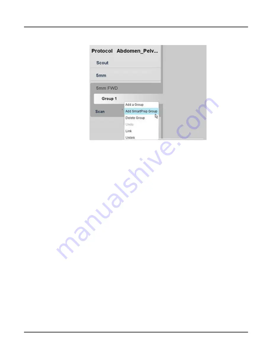
Illustration 10:  SmartPrep option on the right mouse menu

2. If the diagnostic scan tasks are not confirmed, confirm the settings for these groups. After

the last is confirmed, the SmartPrep Setup window opens.

3. From the scout localizer on the display monitor, click and drag the slice line to define the

Monitor location. Alternatively, type in the S/I location in the Monitor Location text field in the

Baseline and Monitor Collection, for example, 

S110

.

4. Expand the Baseline and Monitor Collection and enter the following values:

Revolution CT User Manual

Direction 5480385-1EN, Revision 1

320

3  SmartPrep

Содержание Revolution CT

Страница 1: ...Revolution CT User Manual OPERATING DOCUMENTATION 5480385 1EN Revision 1 ...

Страница 2: ...This page left intentionally blank Revolution CT User Manual Direction 5480385 1EN Revision 1 2 ...

Страница 3: ...ion Date Reason For Change 1 August 2014 Initial release The original language of this document is English Direction Number 5480385 1EN Revision 1 Revolution CT User Manual Direction 5480385 1EN Revision 1 Revision History 3 ...

Страница 4: ...Revolution CT User Manual Direction 5480385 1EN Revision 1 This page left intentionally blank 4 Revision History ...

Страница 5: ...al Safety Guidelines 45 2 Safety Conventions 47 3 Symbols and Warning Labels 48 3 1 Symbols 48 3 2 Equipment Warning Labels 52 3 2 1 Laser Warning Labels 52 3 2 2 X ray Warning Labels 53 3 2 3 Table Warning Labels 53 3 2 4 Power Distribution Unit PDU Warning Labels 54 3 2 5 Scanner Desktop Labels 55 3 2 6 External Accessory Labels 55 4 Radiation Safety 59 4 1 X Ray Protection 59 4 2 General Radiat...

Страница 6: ...4 10 1 Emergency Devices 74 10 1 1 Emergency Stop 74 10 1 2 System Emergency OFF Buttons using Main Disconnect Control 75 10 2 Emergency Patient Care During X ray ON 76 10 3 Emergency Egress 76 11 Laser Safety 77 12 Reconstructed Image Orientation 79 13 Data Safety 81 14 Application Specific Safety Topics 83 14 1 Axial and Helical Scanning 83 14 2 Cardiac Imaging 83 14 3 CT Integrated Cardiac Modu...

Страница 7: ... 17 1 Monitor Safety 93 17 2 IV Pole Safety 93 17 3 Table Tray Safety 94 17 4 Systems With Metal Free Cradles and Accessories 94 17 5 Power Injector Safety 94 17 6 Phantom Safety 94 18 Maintenance and Cleaning 95 19 Hazardous Substances 96 20 System Performance 97 Chapter 4 READ ME FIRST 99 1 About This Manual 99 1 1 Notices 99 1 2 Purpose of this guide 99 1 3 Prerequisite skills 99 2 Scan Monitor...

Страница 8: ...mall patient doses 123 2 3 1 Perform only necessary CT examinations 123 2 3 2 Scan only the organ or anatomical region indicated 123 2 3 3 Minimize multi phase contrast CT examinations 124 2 3 4 Properly center all patients in the gantry 124 2 3 5 Lower mA settings for chest and bone imaging 124 2 3 6 Scan signal to noise 124 2 3 7 Consider using in plane Bismuth shields 124 2 3 8 Use pediatric po...

Страница 9: ...ons 134 2 1 2 Patient weight and patient size 134 2 1 3 Properly position large patients in the gantry 134 2 2 Guidelines for adjusting individual exposure parameters by patient 135 2 2 1 Adjust parameters 135 2 2 2 High kV 135 2 2 3 mA adjustment 135 2 2 4 Lower pitch slow rotation time 135 2 2 5 Scan Type 135 2 2 6 Increase slice thickness 136 2 3 Radiation exposure and dose reporting 136 Chapte...

Страница 10: ...2 11 Use the Dose Audit Tool 154 11 1 Display a Dose Check Log 154 11 2 Display the Protocol Summary 154 11 3 Display the Invalid Protocols 154 11 4 Export Dose Check Log Protocol Summary Invalid Protocols Data and User Protocols 154 Chapter 8 EQUIPMENT 157 1 Overview 157 2 Scanner Desktop 158 2 1 Computer 160 2 2 Reconstruction hardware 160 2 3 Monitors 160 2 4 Scan Control Interface and Keyboard...

Страница 11: ...accessories 180 4 3 1 Cradle pad 180 4 3 2 Cradle extender Axial and Coronal head holders 180 4 3 3 Cradle extender pad 181 4 3 4 Patient arm board 181 4 3 5 Catheter bag holder 181 4 3 6 Table tray 181 4 3 7 IV pole 181 4 3 8 Positioning straps 181 5 Hardware Components 183 5 1 Components 183 5 2 Coverage 183 5 3 Axial interval 183 5 4 Helical pitch scan mode and collimation 183 5 5 Detector conf...

Страница 12: ...up from system shutdown 195 2 3 3 Start up from power off 196 2 3 4 System start up failures 196 2 4 Shut down or restart the system 196 2 4 1 Considerations 196 2 4 2 Shutdown process 196 2 4 3 Restart process 197 3 Daily Quality Assurance 198 3 1 Tube Warmup 198 3 2 Calibration 198 3 2 1 Daily calibration 198 3 2 2 Full system calibration 198 3 2 3 Non GE X ray tube 198 3 3 Daily QA workflow 199...

Страница 13: ...210 2 9 Search for a Patient on the Schedule 211 2 10 HIS RIS Search 211 2 11 Setting up the HIS RIS Refresh 213 2 12 Update the patient schedule 215 Chapter 11 SCAN 217 1 Overview 217 2 Scan Theory 218 2 1 Dose Deterministic Effects 218 2 2 CT Perfusion 220 2 2 1 Purpose of CT Perfusion 220 2 2 2 Components of a CT Perfusion Study 221 2 2 2 1 Body perfusion considerations 221 2 2 2 2 Perfusion ac...

Страница 14: ...ng 228 2 4 7 AEC considerations of patient size shape composition and age 229 2 4 8 Dynamic AEC scanning 229 2 4 9 How to tell if the dose has changed 229 2 4 10 Summary 229 2 4 11 AEC Messaging 230 2 5 Slice Thickness Reference Noise Index and Noise Index Values 231 2 6 SmartmA ODM 232 2 6 1 SmartmA 232 2 6 1 1 SmartmA background 232 2 6 1 2 SmartmA theory 233 2 6 1 3 References 234 2 6 1 4 Smart...

Страница 15: ...with the bar code reader 254 3 3 2 2 Modify the Patient Information presets 254 3 3 3 Select a protocol 255 3 3 4 Acquire a scout 256 3 3 5 Adjust the Graphic Rx 257 3 3 6 Enter contrast descriptions 261 3 3 6 1 Selecting a contrast preset 262 3 3 6 2 Adding a contrast preset 262 3 3 7 Start a scan 262 3 3 8 Duplicate a series 264 3 3 9 Stop a scan 264 3 3 9 1 Abort a scan in progress 264 3 3 9 2 ...

Страница 16: ...y Selection 276 4 5 Scan parameters workflow 277 4 5 1 Choose the Scan Type 279 4 5 2 Set the Coverage Speed options 280 4 5 3 Set the kV and mA Control 281 4 5 3 1 Set the mA 281 4 5 3 2 Set the kV 282 4 5 4 Set the Anatomy Selection 283 4 5 4 1 Set the Start and End Locations 283 4 5 4 2 Set the Scan Field of View 283 4 5 4 3 Set the Display Field of View DFOV for the primary recon 284 4 5 4 4 S...

Страница 17: ...py Forward 291 6 2 Primary Recon collection 291 6 3 Primary Recon parameters workflow 293 6 3 1 Set the Slice Thickness 293 6 3 2 Set the Image Interval 293 6 3 3 Set the Recon Type 294 6 3 4 Set Recon Options for Helical scan types 295 6 3 4 1 Recon Mode 295 6 3 4 2 IQ Enhance 295 6 3 5 ASiR V for all scan types 295 6 3 6 Adjust Window Width and Window Level for all scan types 295 6 3 7 Image Fli...

Страница 18: ...dulation ODM 304 8 3 4 AEC with Cardiac Modes 304 8 3 5 SmartHelical 305 8 3 6 Advanced Artifact Reduction AAR 305 8 3 7 Adaptive Statistical Iterative Recon ASiR V 305 8 3 8 kV Assist 305 8 3 9 Auto Gating Configuration 305 8 3 10 Dose Reports 305 8 4 View the Dose Report 305 8 4 1 Prerequisites 305 8 4 2 Dose Report Generation 305 8 5 Dose Information 306 Chapter 12 SCAN APPLICATIONS 307 1 Overv...

Страница 19: ...Dynamic Transition 324 3 5 1 Baseline Phase with Dynamic Transition 324 3 5 2 Monitor Phase with Dynamic Transition 324 3 6 Scan Phase Diagnostic Scan 325 4 Enhanced Xtream Injector 326 4 1 About Enhanced Xtream Injector 326 4 1 1 Indications for use 326 4 1 2 Protocol considerations 326 4 2 Enhanced Xtream Injector window 326 4 3 Contrast report 329 4 4 Set up the Enhanced Xtream Injector 329 Cha...

Страница 20: ...ng scan 340 2 6 Acquire a contrast enhanced cardiac scan 342 3 Cardiac Scan Parameters 345 3 1 Scan Type 345 3 2 Primary Recon 345 3 3 Secondary Recon 345 3 4 Cardiac scan modes 345 3 4 1 Anatomy Selection 346 3 4 1 1 Considerations 346 3 4 1 2 Graphic Prescription Graphic Rx 346 3 4 2 Scan Overlap 347 3 4 3 Single Table Position 347 3 5 Set the ECG and Gating settings 347 3 5 1 Auto Gating 348 3 ...

Страница 21: ...rd the heart rate during breath hold 360 5 5 Manual Mode 360 6 Cardiac Recon 362 6 1 Cardiac QC Recon 362 6 2 Primary Recon 362 6 3 Recon Link to Auto Gating 362 6 4 Prescribing Basic Cardiac Secondary Recons 362 6 5 Interactive ECG Editor 364 6 6 Graphically adjust reconstruction timing 365 6 6 1 Method 1 365 6 6 2 Method 2 365 6 6 3 Method 1 and 2 365 6 7 Insert delete or move an R peak trigger ...

Страница 22: ...d Image Processing Task List 382 2 3 1 Auto View 382 2 3 2 Viewport Priority 382 2 4 View images in a cine loop 382 2 5 View a reference image 384 3 Image Tools 386 3 1 Display normal 386 3 2 Edge smoothing and lung enhancement filters 386 3 2 1 Considerations 387 3 2 2 Applying filters 388 3 3 Gray Scale Enhancement 388 3 4 Flip rotate images 390 3 5 DICOM Gray Scale Presentation State GSPS objec...

Страница 23: ...t page 399 5 3 Hide show or remove graphics 400 5 4 Save an image screen 401 5 5 Cross reference images on a scout 401 5 6 Command Line 402 6 User Preferences 406 6 1 Set annotation preferences 406 6 2 Set series binding preferences 409 Chapter 15 DISPLAY APPLICATIONS 411 1 Overview 411 2 Add Subtract 412 2 1 Add Subtract basic terminology 412 2 2 Add Subtract and Image Combination window 412 2 3 ...

Страница 24: ...ormat 428 3 2 3 Manual reformat 429 3 2 4 Graphic object for oblique reformats 429 3 2 5 Graphic object for rotate reformats 430 3 2 6 Modify active yellow annotation 431 3 2 7 3D cursor 432 4 Exam Split 434 4 1 Exam Split Configuration 434 4 1 1 Virtual mode 434 4 1 2 Hard mode 434 4 2 Selecting exams to be split 434 4 3 Split exams when the scan is completed 435 Chapter 16 REFORMAT 441 1 Overvie...

Страница 25: ...tions 446 3 Display 448 3 1 Annotation 448 3 2 ROI 449 3 3 Modify active red annotation 449 3 4 Review Controller screen 451 3 5 Display tab 453 3 6 My Tools tab 455 3 6 1 View Tools 455 3 6 2 Remove a tool 456 3 6 3 Add a tool 456 3 6 4 Move or hide the palette 456 3 7 Color Map Table screen 456 3 8 ROI Preferences screen 458 3 9 Annotate an image 459 3 10 Save preset annotation 460 3 11 Measure ...

Страница 26: ... Settings screen 470 5 6 VR Controls screen 472 5 7 Display a VR image 474 5 8 Attach detach objects 475 5 9 Cut planes 476 5 10 Work with colors 477 5 10 1 Add colors 477 5 10 2 Assign a range of colors 478 5 10 3 Change a color 478 5 11 Autofit 478 5 12 Create a multi VR object 479 5 13 Modify the opacity ramp 480 5 14 Zoom in out 481 6 Segment 482 6 1 Segment tab 482 6 2 Scalpel control panel 4...

Страница 27: ...h film images 499 7 9 1 Rotate 360 3D images 499 7 9 2 Radial planes on 2D views 500 7 10 Save a curved parallel plane or rotating curve batch 501 Chapter 17 DATA MANAGEMENT 503 1 Overview 503 2 File Manager 504 2 1 Controls area 505 2 1 1 Local Remote Exam List Selection 506 2 1 2 Search box 506 2 1 3 Source menu 507 2 1 4 Application icons 507 2 1 5 Recycle Bin 508 2 2 Exam list 509 2 2 1 Exam l...

Страница 28: ...leting series and images 516 2 3 3 Configuring the Series List 517 2 3 3 1 Choosing which columns to display 517 2 3 3 2 Changing the width of columns 517 2 3 3 3 Changing the order of columns 517 2 3 4 Keyboard shortcuts 517 3 Job Management Screen 519 4 Archive Network 522 4 1 Configure Network Hosts window 523 4 1 1 Configured Hosts list 523 4 1 2 Remote Host Information 524 4 1 3 Archive Node ...

Страница 29: ...idge 541 6 Data Export 543 6 1 Compose Tab 543 6 2 Export Tab 547 6 3 Compose a Report 552 6 4 Export a Report 552 6 5 View a Report on a PC 553 6 6 Delete Items 554 7 Patient Data 555 8 Scan Data Manager 561 8 1 Locking and unlocking scan data 563 8 2 Deleting scan data 563 8 3 Add reconstruction 563 8 4 Save full or anonymized raw scan data 563 9 Recon Management 565 9 1 Recon Management concept...

Страница 30: ...onstruction and Image Processing Task List 570 10 4 1 Auto View 571 10 4 2 Series Binding 571 10 4 3 Expanded Mode 571 10 4 4 Viewport Priority 571 10 5 Image Tools Column 571 10 6 Data Transfer 573 Chapter 18 PROTOCOLS 575 1 Overview 575 2 Protocols 576 2 1 Build protocols 576 2 2 Use protocols 576 2 3 Edit protocols 577 2 4 View protocols 577 2 5 System options 577 2 6 Protocol Selection window ...

Страница 31: ...ration 590 5 1 Auto Gating workflow 590 5 2 Set up a User Profile 590 5 2 1 Open Auto Gating Configuration 590 5 2 2 Set up the HR configuration 590 5 3 Build a cardiac protocol using Auto Gating 591 6 Dose Reporting in Protocol Management 592 Chapter 19 ACCESS CONTROLS 593 1 Overview 593 2 Access Controls 594 2 1 Introduction 594 2 2 Users and groups 594 2 3 Groups and privileges 594 2 4 Open EA3...

Страница 32: ...gure the Enterprise tab 607 2 17 Auto configuration 609 2 18 Manual configuration 611 Chapter 20 SYSTEM MANAGEMENT 613 1 Overview 613 2 System Tools 614 2 1 Using Message Viewer 614 2 2 Apply Product Network Filters 615 2 3 Find third party software license 616 3 System Preferences 617 3 1 Introduction 617 3 2 Set Viewport Preferences 618 3 2 1 Set annotation preferences 618 3 2 2 Set Window Width...

Страница 33: ...ral Preferences 629 3 8 1 Set Screensaver Time 629 3 8 2 Set the Scan Room Playback Volume 629 3 8 3 Set the Patient Information Display 630 3 8 4 Set the Extended Hounsfield Units HU 630 3 9 Set PPS Preferences 631 4 System Troubleshooting 632 4 1 Open a Unix shell 632 4 2 Collect Data with SPR Snap 633 4 3 Use iLinq 634 4 3 1 Launch iLinq 634 4 3 2 Terminate iLinq remote connection 634 Chapter 2...

Страница 34: ... 641 4 4 Required characteristics and configuration for network support of Revolution CT Scanner specifications 644 4 4 1 Remote Host Parameters 644 4 4 2 Archive Node Settings 644 4 5 Network Compatibility 644 4 6 Hazardous Situations Due to Failure of IT network 646 5 System Operational Modes 648 5 1 Overview 648 5 2 Scout 648 5 3 Axial 648 5 4 Cine 648 5 5 Helical 649 5 6 Cardiac Axial 649 5 7 ...

Страница 35: ...MEASURE 677 1 Units of Measure 677 Appendix D LEXICON 681 1 Lexicon 681 1 1 Scan acquisition and user interface basics 682 1 2 Dose modulation and reduction tools 683 1 3 Multi slice detector geometry 683 1 4 Image reconstruction and display 684 1 5 Contrast media tools 685 1 6 Multi planar formats and 3D processing 686 1 7 Service and application tools 686 1 8 Workflow 687 1 9 References 687 Appe...

Страница 36: ...Appendix F AUTO GATING PROFILES 691 1 Auto Gating Profiles 691 Revolution CT User Manual Direction 5480385 1EN Revision 1 36 Table of Contents ...

Страница 37: ...s potential safety problems and how to avoid them Everyone who uses this equipment must read and understand all instructions precautions and warnings Procedures and safety precautions described in the Safety chapter should be read periodically Only designated persons service personnel are to install this system They are to refer to the proper pre installation and installation manuals when installi...

Страница 38: ...Tips and Workarounds This manual details workaround information for software and system information Accessing User Documentation The system user information is designed to provide you with safety and operation information for you to safely and effectively use the system To start the user information Insert the disk you wish to view in the DVD RW DVD RAM drive in the media tower Click the icon and ...

Страница 39: ... Patient contrast injector For Enhanced Xtream Injector Option Nemoto Dual Shot Alpha CiA425 Class IV GE 5328195 Nemoto Dual Shot GX CiA425 Class IV Medrad ISI900 for Stellant D Class IV GE 5335919 Patient comfort and workflow accessories such as the cradle pad cradle extender patient arm board catheter bag holder table tray and IV pole attached to the cradle Patient positioning accessories includ...

Страница 40: ...Revolution CT User Manual Direction 5480385 1EN Revision 1 This page left intentionally blank 40 3 GE Approved Accessories ...

Страница 41: ...hould be used only with GE approved equipment The Revolution CT system complies with IEC 60601 1 1 2000 All portions of the Revolution CT system are suitable for use in the patient environment The system should be used only with GE approved equipment The Revolution CT system complies with radiation protection in accordance with IEC 60601 1 3 2008 The Revolution CT system complies with radiation pr...

Страница 42: ...ices when it bears the following CE marking of conformity Authorized representative for Europe European registered place of business GE Medical Systems SCS Quality Assurance Manager 283 rue de la Minière 78530 BUC France Tel 33 130704040 Revolution CT User Manual Direction 5480385 1EN Revision 1 42 1 Applicable Regulations and Standards ...

Страница 43: ...an techniques from patients of all ages These images may be obtained either with or without contrast This device may include signal analysis and display equipment patient and equipment supports components and accessories This device may include data and image processing to produce images in a variety of trans axial and reformatted planes Further the images can be post processed to produce addition...

Страница 44: ...CT product Table 1 Revolution CT Product Manufacturer Model Name Manufacturer Manufacturing Site Manufacturer Address Revolution CT GE Medical Systems 3000 N Grandview Blvd Waukesha WI 53188 USA Revolution CT User Manual Direction 5480385 1EN Revision 1 44 3 Product Manufacturer ...

Страница 45: ...he act of reading this manual renders the reader qualified to operate test or calibrate the system The owner should make certain that only properly trained fully qualified personnel are authorized to operate the equipment A list of authorized operators should be maintained This manual should be kept at hand studied carefully and reviewed periodically by the authorized operators Unauthorized person...

Страница 46: ...itations These limitations must be considered before making any decision based on quantitative values In case of doubt please consult your sales representative Do not block the ventilation ports of the electronic equipment Always maintain at least 6 inches 15 cm clearance around the ventilation ports to prevent overheating and damage to the electronic hardware The supplier will make available on r...

Страница 47: ...EVERE PERSONAL INJURY OR SUBSTANTIAL PROPERTY DAMAGE IF YOU IGNORE THESE INSTRUCTIONS CAUTION This label applies to conditions or actions that have potential hazard You may cause minor injury or property damage if you ignore these instructions This manual uses pictures or icons to reinforce the printed message It uses the corresponding international symbol or icon next to the danger warning or cau...

Страница 48: ...age Table 1 Symbols Used in Labeling Symbol Description Alternating current 3 Phase alternating current Protective earthing point ON Power ON OFF Power OFF Input power Output Power Type B applied part Functional earth ground Electrical shock hazard Revolution CT User Manual Direction 5480385 1EN Revision 1 48 3 Symbols and Warning Labels ...

Страница 49: ...other safety stand ards to North American safety standards Authorities Having Jurisdic tion AHJs in 50 states and Canada and retailers accept the ETL classified and recognized as proof of product safety The system shall conform to applicable requirements of 21CFR Subchapter J Revolution CT User Manual Direction 5480385 1EN Revision 1 Chapter 3 Safety 49 ...

Страница 50: ...vant European health safety and environmental protection legislation Table 2 Symbols Used in Labeling Symbol Description Made for Indicates the manufacturer responsible design owner Made by or by Indicates the manufacturing Location Refer to instruction manual booklet Attention consult accompanying documents Pushing prohibited Do not stand on table foot cover IEC Manufacture location label Revolut...

Страница 51: ... Serial number Catalog number X Ray filtration Al Equivalent Filtration Minimum filtration Laser symbol Extra large focal spot Large focal spot Small focal spot Revolution CT User Manual Direction 5480385 1EN Revision 1 Chapter 3 Safety 51 ...

Страница 52: ...10 g 4 CAUTION LASER RADIATION DO NOT STARE INTO BEAM CLASS 2 LASER PRODUCT CAUTION Laser Radiation Do Not Stare into Beam 635 670nm Laser Diode 1 Milliwatt Maximum Output Class II Laser Product Illustration 2 Labels on the front of the gantry Reference 21CFR 1040 10 h CAUTION LASER APERTURE Do not stare into beam Revolution CT User Manual Direction 5480385 1EN Revision 1 52 3 Symbols and Warning ...

Страница 53: ... Illustration 4 Label located on Scan Control Interface Reference 21CFR 1020 30 j WARNING THIS X RAY UNIT MAY BE DANGEROUS TO PATIENT AND OPERATOR UNLESS SAFE EXPOSURE FACTORS OPERATING INSTRUCTIONS AND MAINTENANCE SCHEDULES ARE OBSERVED TO BE USED BY AUTHORIZED PERSONNEL ONLY 3 2 3 Table Warning Labels Illustration 5 Pinch warning label located on the table Revolution CT User Manual Direction 548...

Страница 54: ...ING AVOID INJURY DO NOT EXCEED TABLE MAXIMUM CAPACITY OF 227 KG 500 LB 3 2 4 Power Distribution Unit PDU Warning Labels Illustration 7 PDU move warning on back of PDU WARNING PDU CAN MOVE AND DAMAGE CABLES DO NOT LEAN ON OR MOVE WHEN CONNECTED TO POWER Illustration 8 PDU move caution on back of PDU Revolution CT User Manual Direction 5480385 1EN Revision 1 54 3 Symbols and Warning Labels ...

Страница 55: ...ng CAUTION Avoid Injury Read and understand information in manuals before operating product Illustration 11 WEEE Label 3 2 6 External Accessory Labels Illustration 12 IV pole caution label on leg of IV pole CAUTION Do not load more than 4 5 kg or 10 pounds Verify that extension collar is securely tightened before use Revolution CT User Manual Direction 5480385 1EN Revision 1 Chapter 3 Safety 55 ...

Страница 56: ...S SECURELY TIGHTENED BEFORE USE Illustration 14 Table tray caution label on leg of table tray CAUTION Do not load more than 9kg or 20 lbs You may also see this statement as a warning Illustration 15 Table tray warning label on leg of table tray WARNING DO NOT LOAD MORE THAN 9 KG OR 20 POUNDS Revolution CT User Manual Direction 5480385 1EN Revision 1 56 3 Symbols and Warning Labels ...

Страница 57: ... or 75 pounds You may also see this statement as a warning Illustration 17 Axial head holder warning WARNING FALL HAZARDS ACCESSORY MAY FALL AND CAUSE INJURY IF NOT LATCHED TO CRADLE MAKE SURE THAT ACCESSORY IS LATCHED TO UNDERSIDE OF CRADLE EXCESSIVE WEIGHT CAN BREAK ACCESSORY AND CAUSE INJURY DO NOT LOAD MORE THAN 34 KG 75 LBS Illustration 18 Coronal head holder caution Revolution CT User Manual...

Страница 58: ...RY IF NOT LATCHED TO CRADLE MAKE SURE THAT ACCESSORY IS LATCHED TO UNDERSIDE OF CRADLE EXCESSIVE WEIGHT CAN BREAK ACCESSORY AND CAUSE INJURY DO NOT LOAD MORE THAN 34 KG 75 LBS Illustration 20 Bumperless extender warning WARNING FALL HAZARDS ACCESSORY MAY FALL AND CAUSE INJURY IF NOT LATCHED TO CRADLE MAKE SURE THAT ACCESSORY IS LATCHED TO UNDERSIDE OF CRADLE EXCESSIVE WEIGHT CAN BREAK ACCESSORY AN...

Страница 59: ...hemselves or others to radiation Everyone having anything to do with X ray equipment must receive proper training and become fully acquainted with the recommendations of the National Council on Radiation Protection and Measurements and the International Commission on Radiation Protection NCRP reports are available from NCRP Publications 7910 Woodmont Avenue Room 1016 Bethesda Maryland 20814 WARNIN...

Страница 60: ...ECAUTIONS BEING UTILIZED Stay behind a lead screen or lead glass shield during each X ray exposure Use technique factors prescribed by the radiologist or diagnostician Use a dose that produces the best diagnostic results with the least X ray exposure The x ray exposure indicator is an amber light located on the secondary gantry display on the front and rear of the gantry directly below the primary...

Страница 61: ...s selected for the following scan types SmartPrep Cine or Axial scans with zero table increment scan interval WARNING THIS SERIES CONTAINS ONE OR MORE GROUPS WITH MULTIPLE SCANS AT THE SAME TOMOGRAPHIC PLANE I E SAME LOCATION DO YOU WANT TO CONTINUE After reading the message if you wish to continue with the scan click Continue otherwise click Cancel WARNING PROLONGED EXPOSURE TO X RAY IN ONE SPOT ...

Страница 62: ...you setup the scan parameters from the Scan Settings screen the Dose Information area at the bottom center of the scan monitor contains updated dose information This dose information is based on a measurement of the CTDI or CT Dose Index which is the current standard for CT dosimetry and performance By using a measurement called CTDIvol a single value is provided to estimate the relative dose for ...

Страница 63: ... dose is generally a very small part of the exam The dose information updates when technique values such as kV mA scan time slice thickness and scan field of view are changed Dose information is saved as a screen save image in Series 999 upon selecting End Exam Series 997 contains the DICOM Dose Structured Report Revolution CT User Manual Direction 5480385 1EN Revision 1 Chapter 3 Safety 63 ...

Страница 64: ...ice for more than a few seconds attending staff should be ready to take emergency measures to treat adverse reactions if they occur 5 2 Recommendations after scanning Have the patient turn the device back on if it had been turned off prior to scanning Have the patient check the device for proper functioning even if the device was turned off Advise the patient to contact his or her healthcare provi...

Страница 65: ...SURE THE EQUIPMENT IS CONNECTED TO A SUPPLY MAINS WITH A PROTECTIVE EARTH IF YOU HAVE ANY QUESTIONS ABOUT THESE REQUIREMENTS CONTACT GE HEALTHCARE FUSES BLOWN WITHIN 36 HOURS OF BEING REPLACED MAY INDICATE MALFUNCTIONING ELECTRICAL CIRCUITS WITHIN THE SYSTEM HAVE THE SYSTEM CHECKED BY QUALIFIED SERVICE PERSONNEL AND DO NOT ATTEMPT TO REPLACE ANY FUSE DANGER INFORMATION ON INTERNAL GANTRY COMPONENT...

Страница 66: ...ies should not exceed 960 watts CAUTION Included power cord is only to be used when connecting GE approved accessories to the gantry or scanner desktop A CT System combined with GE approved accessories complies with the IEC 60601 1 standards related to safety and performance of medical electrical systems Refer to the standard for more information Do not connect electric devices to the CT System th...

Страница 67: ...icator display the crescent moon will be statically lit no flashing Power Distribution Unit Indicator Location PDU light at the front System ON The light indicator will be ON Shutdown The light indicator will be ON Scanner Desktop Indicator Locations Monitors Power ON OFF buttons lights Scanner Desktop NIO Cabinet power on off light located at the front System ON The light indicators will be ON Sh...

Страница 68: ...he Technical Reference Manual Use of RF Radio Frequency sources that intentionally transmit such as cellular telephones transceivers radio controlled products or other RF emitting equipment may cause performance outside the system s published specifications or other adverse operation Revolution CT User Manual Direction 5480385 1EN Revision 1 68 7 Electromagnetic Compatibility Safety ...

Страница 69: ...OT SUITABLE FOR USE IN THE PRESENCE OF A FLAMMABLE ANESTHETIC MIXTURE WITH AIR OR IN THE PRESENCE OF A FLAMMABLE ANESTHETIC MIXTURE WITH OXYGEN OR NITROUS OXIDE Revolution CT User Manual Direction 5480385 1EN Revision 1 Chapter 3 Safety 69 ...

Страница 70: ...F 227 KG 500 LB THIS COULD CAUSE THE TABLE TO FAIL AND THE PATIENT COULD FALL Illustration 23 Warning label located on table WARNING AVOID INJURY DO NOT EXCEED TABLE MAXIMUM CAPACITY OF 227 KG 500 LB CAUTION Temporal sampling may be degraded due to changes in timing for the table to move from location to location if proper positioning methods are not followed Make sure that the patient is securely...

Страница 71: ...IENT TUBING OR IV WARNING CHECK TO MAKE SURE THE POWER INJECTOR HAS ENOUGH IV TUBING TO ALLOW FREE MOVEMENT OF THE CRADLE MAKE SURE THE UNIT ITSELF DOES NOT INTERFERE WITH TABLE TRAVEL ENSURE EXCESS TUBING LENGTH IS SECURED TO THE TABLE TOP DO NOT LOOP ADDITIONAL IV TUBING IN THE PATIENT S FINGERS Check the length of all patient health lines IV tubing oxygen line etc and make sure they accommodate...

Страница 72: ...OES NOT STOP PRESS THE EMERGENCY STOP SWITCHES ON THE CONSOLE OR GANTRY WARNING THE HEAD HOLDER MAY CRACK POSSIBLY INJURING THE PATIENT S HEAD OR NECK IF THE PATIENT TRIES TO BRACE HIMSELF OR HERSELF ON THE HEAD HOLDER DURING POSITIONING THE HEAD HOLDER AND CRADLE EXTENDER ARE ONLY DESIGNED TO SUPPORT 75 POUNDS 34 KG ASK THE PATIENT TO MOVE UP INTO THE HEAD HOLDER OR MANUALLY HELP THE PATIENT INTO...

Страница 73: ...receives cooling air through the air inlets Blocking the air inlets leads to a reduction in air flow and potentially overheating of the system The minimum distance to any object blocking the flow shall be 75 mm 3 inches Critical objects are jackets robes lab coats bed sheets pillow cases covers or blankets that can get sucked into the air inlet and provide an excellent blockage and seal for air fl...

Страница 74: ...antry motion and generation of X rays The system aborts any acquisitions in progress and data obtained prior to the abort can become corrupt or lost Use the System Emergency OFF button for catastrophic emergencies such as fire or earthquake CAUTION If you press the Emergency Stop or Emergency OFF buttons during a scan the system will abort the data acquisition 10 1 1 Emergency Stop NOTE Every oper...

Страница 75: ...every two seconds Press the Reset gantry control button to restore power to the gantry and table When Emergency Stop is applied the maximum stopping distance of the moving cradle is 10 mm Emergency Stop Button Symbols Emergency Stop buttons may be accompanied by one of the symbols below 10 1 2 System Emergency OFF Buttons using Main Disconnect Control In the event of a fire flood earthquake or any...

Страница 76: ...k into the scan room and press the Reset button on the Gantry Control Panel 10 2 Emergency Patient Care During X ray ON Press STOP SCAN to abort X ray and stop gantry table movement Press PAUSE SCAN to pause scanning after the current scan completes During an exam the system pauses between scans if you Press any button on the control panel other than the alignment lights It stops X ray if you Pres...

Страница 77: ...tomic reference point is the sternal notch then the sternal notch would be centered to the laser alignment light For Internal Landmark the gantry displays a table location of 0 mm This sets the zero point for which S and I scan locations are centered around For External Landmark the gantry displays a table location approximately 240 mm from the internal landmark depending on table characterization...

Страница 78: ...hts do not require user maintenance Qualified service personnel must inspect the lights periodically to assure proper alignment CAUTION Laser Radiation Do not view directly with optical instruments Do not expose users of telescopic optics Class 1M laser product Max power 0 39mW Wavelength 635nm IEC 60825 1 2007 03 Revolution CT User Manual Direction 5480385 1EN Revision 1 78 11 Laser Safety ...

Страница 79: ...anned Head First and Prone the patients s Left is on the viewer s Left and the patient s Right is on the viewer s Right The image presentation will need to be modified to display preferred anatomical viewing Some viewing stations may not have the capability to flip the image presentation but if the capability exists you must use display tools such as Flip to change the presentation of the image So...

Страница 80: ...THE SYSTEM POSTS A WARNING MESSAGE IF PATIENT ORIENTATION HAS BEEN CHANGED OR DOES NOT MATCH AFTER START OF EXAM Revolution CT User Manual Direction 5480385 1EN Revision 1 80 12 Reconstructed Image Orientation ...

Страница 81: ...ND UNRESERVE OBSOLETE SCAN DATA WARNING DO NOT LOAD ANY NON GE APPROVED SOFTWARE ONTO THE COMPUTER WARNING THE SYSTEM POSTS A WARNING MESSAGE IF THERE IS A FAILURE DURING THE ARCHIVE OF PATIENT DATA WARNING THE SYSTEM POSTS A WARNING MESSAGE IF THERE IS A FAILURE DURING THE NETWORK TRANSFER OF PATIENT IMAGE DATA WARNING LOW IMAGE SPACE PLEASE REMOVE IMAGES AND EMPTY THE RECYCLE BIN WARNING MISSING...

Страница 82: ... is in the User Manual CAUTION When comparing GE CT images with other images consult the DICOM Conformance Statement for the details on the DICOM Image Position Frame of Reference UID and Slice Location values stored CAUTION Some annotation values are stored in private DICOM elements When viewing images on a remote station these annotations values may not be visible on the image Consult the DICOM ...

Страница 83: ...EANS TO DISTINGUISH BETWEEN POTENTIAL ARTIFACT OR PATIENT PATHOLOGY 14 2 Cardiac Imaging CAUTION A patient with any of the conditions list below may require additional attention If patients are scanned with these conditions the software may not be able to detect the R Peaks and the images therefore may be produced as ungated segment images Patient with multiple pre contractions or extra systole e ...

Страница 84: ...r lead placements or a lead falling off during the scan It is important to place new leads on the patient before the scan Make sure the leads are attached properly and use only GE recommended ECG leads It is important to confirm ECG trace clarity before the scan CAUTION If during the scan the heart rate drops significantly lower than the prescribed heart rate there is a potential for gaps in the g...

Страница 85: ...GE IMAGES CAN EASILY BE IDENTIFIED BY THE CORRESPONDING IMAGE ANNOTATION FOLLOW THE DICOM ACQUISITION PARAMETER GUIDELINES LISTED IN EACH APPLICATION USER GUIDE CONSULT GE PUBLISHED DICOM CONFORMANCE STATEMENT OF VOLUME VIEWER NOTE THIS IS AVAILABLE VIA THE INTERNET ON THE GE HEALTHCARE HOME PAGE PRODUCTS INTEROPERABILITY DICOM CONFORMANCE 14 5 Measurements CAUTION The report cursor shows the voxe...

Страница 86: ... KEEP OBJECT AUTOSELECT FLOATER FILTERS ALWAYS MAKE SURE THAT IT WILL NOT REMOVE PATHOLOGIES OR OTHER ESSENTIAL ANATOMICAL STRUCTURES WARNING WHEN USING ANY SEGMENTATION TOOLS AUTOSELECT THRESHOLD PAINT ON SLICE QUICK PAINT CHECK CONTOURS TO CHECK THE RELIABILITY OF THE SEGMENTATION MAKE SURE THE CONTOURS MATCH THE CORRECT SEGMENTATION AND VOLUMES CHECK THAT THE SEGMENTED VOLUMES MATCH THE CONTOUR...

Страница 87: ...this description matches the saved images CAUTION Check with original dataset the reliability of segmentations and measurements performed in Saved objects after post processing and reloading Revolution CT User Manual Direction 5480385 1EN Revision 1 Chapter 3 Safety 87 ...

Страница 88: ...ication Software Safety CAUTION Do not initiate an SPR Snap if the system is actively collecting data with X ray on Revolution CT User Manual Direction 5480385 1EN Revision 1 88 15 Application Software Safety ...

Страница 89: ... and Y in Illustration 31 below assume a scout scan plane of 0 degrees If the scout plane is rotated then the X and Y orientation changes accordingly For measurements of anatomy in the X direction that are at ISO center Y The measure error using the straight line distance graphic is less than 5 of the measured distance plus 2 mm For measurements of anatomy in the X direction that are NOT at ISO Y ...

Страница 90: ...asure Angle CAUTION Measurement accuracy using the angle graphic is equal to the displayed angle value 10 degrees for an angle measured between segments which are five times larger than the image pixel size Accuracy improves as the length of the segments increases Revolution CT User Manual Direction 5480385 1EN Revision 1 90 16 Accuracy of Measurements ...

Страница 91: ...ible System and patient variables may affect CT Number accuracy If you rely solely upon CT numbers without taking variables into consideration you could misdiagnose an image 16 6 CT Number Reference 1020 33 j 1 1020 33 j 2 Besides anatomic location and area each CT pixel also represents a CT number which in turn indicates tissue density An image pixel represents a three dimensional volume or voxel...

Страница 92: ...contained within the ROI and the area of the ROI It also provides the capability to draw and edit a circular region of interest with the ability to calculate and report the mean value standard deviation minimum maximum and area mm2 of the image pixel data contained within the ROI 16 6 2 CT Number Accuracy CT Number of water 0 HU 3 HU CT Number of air 1000 HU 10 HU 16 7 Range Precision and Accuracy...

Страница 93: ...ARM BOARDS AND CATHETER BAG HOLDERS ARE NOT SECURED TO GANTRY AND MAY INTERFERE WITH GANTRY IF NOT POSITIONED PROPERLY 17 1 Monitor Safety CAUTION For a two monitor configuration it is necessary to check the monitor calibration regularly to ensure images are displayed identically on both monitors 17 2 IV Pole Safety Care should be taken in the amount of weight placed on the pole Ensure that the po...

Страница 94: ...he catch on the cradle before attempting to attach the accessory for the first time 17 5 Power Injector Safety CAUTION The injector and the system are operated independently after the Start Scan button is pressed When you want to stop both the system and the injector use the Stop Scan button on the Scan Control Interface and the stop injector function on the injector system 17 6 Phantom Safety WAR...

Страница 95: ...lied cleaning agent wipes Warm water and soap mixture mix 1 gallon of water with 0 5 teaspoon of dish washing soap Common household bleach diluted 10 1 Sani cloth HB Also use dry cleaning for electronic components Do not clean the connectors on the cables for ECG respiratory equipment etc If you need to clean them contact GE Service Planned maintenance must be carried out regularly to ensure safe ...

Страница 96: ...uperation For example it is forbidden to dispose of these oils in the wastewater or sewage system or in the natural environment Your local GEMS field service will advise you on the suitable means of disposal of equipment The X ray Tube Assembly to be discarded should be forwarded to the GEMS Service network and it will be disposed of in a GEMS recycling center Precautions Take all the necessary pr...

Страница 97: ...CAUSE SUBSEQUENT COOLING DELAYS NOTE TUBE WARMUP WILL RUN IN AUTOSCAN MODE CAUTION Prior to the start of fast calibration when an unrecognized X ray tube is detected the system displays the following notification to the operator Attention An unrecognized tube has been installed on the system Fast Calibration techniques are designed specifically for GE tubes and GE cannot guarantee that the perform...

Страница 98: ...Revolution CT User Manual Direction 5480385 1EN Revision 1 This page left intentionally blank 98 20 System Performance ...

Страница 99: ...e the resolution of some type of problem locate the difficulty and make adjustments to solve the problem 1 2 Purpose of this guide This user manual is written for health care professionals and technologists to provide the information needed to properly operate the system The manual is intended to allow you to understand the system components and features and to use the system to its maximum potent...

Страница 100: ... window to create a new patient entry Once the patient information is com pleted and the protocol is selected the Scan Setup window opens Patient Schedule Opens the Patient Schedule to preprogram or retrieve patient information from Digital Imaging and Communications in Medicine DICOM or Hospital Information System Radiology Information Sys tem HIS RIS 2 1 New Patient Click to open the New Patient...

Страница 101: ...ion 1 Patient Information area 2 Protocol Selection area 2 2 Patient Schedule Click to open the Patient Schedule drawer Illustration 3 Patient Scheduler drawer Open Revolution CT User Manual Direction 5480385 1EN Revision 1 Chapter 4 Read Me First 101 ...

Страница 102: ...er Closed Illustration 5 Patient Schedule window 2 3 Scan Setup When an exam is in process the Scan Setup window displays It is divided into the following areas Revolution CT User Manual Direction 5480385 1EN Revision 1 102 2 Scan Monitor ...

Страница 103: ...t the landmark should be set at Indicates the Auto Voice language category 4 Scan Timeline area View prep group delays and real time scan progress information Use the scroll wheel to review all scan groups 5 Scan Task List area The series scanning tasks to complete an exam Task Status No checkmark Not confirmed Blue background Confirmed but not scanned Gray background and checkmark Scanned 6 Scan ...

Страница 104: ...d dose for the exam 11 Dose Display area Displays projected dose information based on current scan settings It also displays other real time in formation when the active application requires it Illustration 7 Image Quality widget Illustration 8 Acquisition Window and Heart Rate widget Illustration 9 Patient Tab Status Number Description 1 Patient waiting to be scanned 2 Patient on the table 3 Open...

Страница 105: ...ogress window Number Description 1 Scan Timeline 2 ECG Trace 3 Scan group parameters 4 Real Time Information Illustration 11 Scan Timeline Revolution CT User Manual Direction 5480385 1EN Revision 1 Chapter 4 Read Me First 105 ...

Страница 106: ...ay Exposure time of all groups Group delay Illustration 12 Real Time Information Number Description 1 Messages for moving table 2 Prep group delay countdown 3 Status of injector 4 Pause Resume control Illustration 13 Done Scanning window PPS enabled Revolution CT User Manual Direction 5480385 1EN Revision 1 106 2 Scan Monitor ...

Страница 107: ...Illustration 14 Done Scanning window PPS disabled Illustration 15 Reports window Revolution CT User Manual Direction 5480385 1EN Revision 1 Chapter 4 Read Me First 107 ...

Страница 108: ... Status area 2 Reconstruction and Image Processing area 3 Image Viewports 4 File Manager 3 1 Icons and System Status Area This area displays the mode icon system utilities icon recon management icon available disk space tube status icon system messages and the date and time It is divided into the following areas Revolution CT User Manual Direction 5480385 1EN Revision 1 108 3 Image Monitor ...

Страница 109: ...tions Protocol Management Protocol Management Auto Gating Configuration Auto Voice Management Access Controls User Admin Tool Dose Check Management Dose Audit Tool System Preferences Learning Solutions Shutdown Switch User Restart Shutdown Revolution CT User Manual Direction 5480385 1EN Revision 1 Chapter 4 Read Me First 109 ...

Страница 110: ...amount of available disk space on the system A warning alerts the user of low disk space NOTE GE recommends that you remove images when the image space falls below 1 000 images This ensures enough disk space for acquiring and reconstruct ing images Do not remove images while scanning restoring or receiving im ages 6 System Messages Click on the message for a list of all system messages 7 Date and ...

Страница 111: ...on and Image Processing window Number Description 1 Task List 2 Add Recon 3 Add Reformat 4 Study based transfer options 5 Image Tools 6 Command Line 7 Task Status 8 Image display assignment indicator Revolution CT User Manual Direction 5480385 1EN Revision 1 Chapter 4 Read Me First 111 ...

Страница 112: ...both the scan monitor and image monitor The four viewports on the image monitor are used for image processing Illustration 20 Image Viewports Illustration 21 Viewport Controls Revolution CT User Manual Direction 5480385 1EN Revision 1 112 3 Image Monitor ...

Страница 113: ...o open the File Manager browser Select exam series images from the patient list and click to launch the session tab Illustration 22 File Manager Open File Manager serves three main functions exam organization and status accessing files and opening an exam Illustration 23 File Manager Closed Revolution CT User Manual Direction 5480385 1EN Revision 1 Chapter 4 Read Me First 113 ...

Страница 114: ... Manager Number Description 1 Controls area 2 Exam list 3 Series list 4 Image display Image list Illustration 25 File Manager Image Navigation Revolution CT User Manual Direction 5480385 1EN Revision 1 114 3 Image Monitor ...

Страница 115: ...Number Description 1 Image list icon 2 Maximize image icon Revolution CT User Manual Direction 5480385 1EN Revision 1 Chapter 4 Read Me First 115 ...

Страница 116: ...ibed on a window 4 3 Button and text appearance Buttons that are gray are inactive Illustration 26 Active Button and Inactive Button Table 2 Text Field Notifications White Background Settings updated by the user display with a white background Underlined Text Text fields that can be changed are underlined Anchored Popover Click the icon next to the parameter to open White Background Red Outline Fo...

Страница 117: ...e Table 3 Gantry Display Indicators Not selected not displayed Use the gantry controls enter key to turn on the selection On not displayed On displayed Use the gantry controls navigation button to toggle between which selection to display 4 4 Pop up windows Pop up windows may require an acknowledgement by clicking OK Accept or Apply to close the window 4 5 Mouse controls The two button mouse with ...

Страница 118: ...e left mouse button while moving the mouse Right click and drag Click and hold the right mouse button while moving the mouse Scroll wheel click and drag Click and hold the scroll wheel while moving the mouse Double click Click the left mouse button twice in rapid succession Triple click Click the left mouse button three times in rapid succession Revolution CT User Manual Direction 5480385 1EN Revi...

Страница 119: ...efore the user interface displays can result in the wrong screen displayed or the wrong value entered If the scanner desktop becomes unresponsive for several minutes click and select Shutdown then Restart to restart the system If you cannot select Shutdown turn off the scanner desktop power switch wait 10 seconds then turn the power switch back on In some cases the system will notify you of errors...

Страница 120: ...Revolution CT User Manual Direction 5480385 1EN Revision 1 This page left intentionally blank 120 5 System Troubleshooting Tips ...

Страница 121: ...atients whenever it is determined that a CT scan is necessary CT is an extremely valuable tool for diagnosing injury and disease but its use is not without risk This chapter discusses the importance of minimizing the radiation dose in small patients and children consistent with ALARA principles Revolution CT User Manual Direction 5480385 1EN Revision 1 Chapter 5 Pediatrics and Small Patients 121 ...

Страница 122: ... Tomography for Pediatric and Small Adult Patients dated November 2 2001 that discuss the value of CT and the importance of minimizing the radiation dose especially in children These documents can be accessed at http www fda gov 2 2 Dose reporting considerations It is widely understood and accepted that adult techniques should never be applied to small patients or pediatrics since smaller objects ...

Страница 123: ...ed Body Small Head Head Small Body 32 cm phantom Medium Body Large Body Cardiac Small Cardiac Medium Cardiac Large 2 3 Minimize pediatric and small patient doses There are several steps that can be taken to reduce the amount of radiation that pediatrics and small patients receive from CT examinations Everyone shares the responsibility of minimizing CT radiation dose Use the following suggestions f...

Страница 124: ...olution dose imaging is typically unnecessary for these types of studies where there is high inherent contrast between the structures being imaged 2 3 6 Scan signal to noise Limit the highest quality images requiring the highest radiation dose to very specific indications such as angiography or visualizing small subtle lesions Studies with higher noise may be just as diagnostic and require lower d...

Страница 125: ...procedure so they know what to expect when they enter the scan room This will aid in patient cooperation and potentially less repeat studies and dose due to patient motion Revolution CT User Manual Direction 5480385 1EN Revision 1 Chapter 5 Pediatrics and Small Patients 125 ...

Страница 126: ...3 2 Pediatric protocols The Pediatric Protocol area was designed to help facilitate protocol selection for pediatric patients by providing age based protocol areas for Head Orbit and Miscellaneous and color coding system for Neck Upper Extremity Chest Abdomen Spine and Pelvis It is highly recommended to place and select pediatric protocols from the pediatric selector based on age height and weight...

Страница 127: ...available a Broselow Luten Tape can also be used to obtain the weight based on the length Once you select the Pediatric selector the Pediatric Protocol List displays Next to the name of the protocol a color icon along with the zone number will be indicated The notes area of the protocol selector will display the zone ranges for weight and length color name and the weight color zone number NOTE Wei...

Страница 128: ...2 0 7 Orange 49 6 to 69 5 22 5 to 31 5 122 0 to 137 0 8 Green 69 5 to 89 3 31 5 to 40 5 137 0 to 150 0 9 Black 89 3 to 121 3 40 5 to 55 3 4 Set up a pediatric or small patient exam Use this procedure each time you start a new patient exam for a pediatric patient It is recommended that you complete the patient information setup before you get the patient on the table to reduce patient table time Th...

Страница 129: ...egory has been selected if you entered a weight The protocols in the selected color code are then displayed accordingly The default weight color selector displays the patient weight entered on the Patient Information screen or the last weight color selection if no patient information was entered If you enter a patient weight on the Patient Information screen and select a color weight that is not c...

Страница 130: ...o not use low kV selections on too large of a patient which can potentially result in compromised image quality Work with your radiologist and medical physicist to establish low kV protocols and patient size limits Refer to CTDI Dose Values and Adjustment Factors in the Dose and Performance chapter of the Technical Reference Manual as a guide for making adjustments to mAs for changes in kV in a pr...

Страница 131: ...e mA procedure in the Scan chapter 3 5 4 Increase the pitch Increase the pitch Increasing the pitch decreases the amount of radiation needed to cover the region indicated usually without compromising the diagnostic quality of the scan Increasing pitch from 1 0 to 1 375 1 decreases dose by a factor of about 27 3 5 5 Use Small SFOV Filters Use the smallest SFOV whenever possible depending on the exa...

Страница 132: ...ths or less in age Small Head SFOV should be used for patients from 1 5 years old to 10 years old Ped Body SFOV supports DFOV s up to 32 cm in diameter Both the Ped Body and Ped Head SFOVs are limited to 42 kW This limits the maximum mA possible to 350 at 120 kVp Revolution CT User Manual Direction 5480385 1EN Revision 1 132 3 Pediatric and small patient scans ...

Страница 133: ...ray attenuation in this patient population The degree of X ray attenuation in these large patients may degrade image quality as the patient size increases using the same scan technique as used for normal sized patients 300 lb 136 kg The system allows patients with weights up to 500 lb 227 kg This section presents the concepts necessary to successfully scan large patients Revolution CT User Manual ...

Страница 134: ... quality If the diameter of the patient in all directions is beyond the imaging capability of the 50 cm SFOV the image quality may be severely degraded and may not be useful for diagnosis if there is full reference channel blockage 2 1 3 Properly position large patients in the gantry Body straps may be useful with certain patients These accessories are sometimes helpful in making the patient more ...

Страница 135: ...oise Under these conditions special projection data dependent filters are applied at various threshold levels to help preserve image quality For more information on SmartmA refer to SmartmA in the Scan Parameters section NOTE If the size of the large patient section is beyond 50 cm SFOV SmartmA technique is not recommended since noise and mA prediction may not always be reliable Manual mA is recom...

Страница 136: ...tion exposure is usually used for very large patients to improve image quality to compensate for dose attenuation It is critical to remember that the body filter only uses the 32 cm CTDI phantom for dose reporting purposes CTDIvol displayed in the Dose Information area on the Scan Settings screen and the Dose Report In other words when looking at the actual absorbed dose for the large patient unde...

Страница 137: ...due to patient sizes and imaging needs another consideration on where to set the notification level will be the frequency in which your practice would want it posted Dose Check also issues an alert when the accumulated dose index would exceed the institution s established range GE has pre populated the system level Alert Value AV at 1000 mGy CTDIvol in accordance with the FDA November 8 2010 lette...

Страница 138: ...hese can be found at www aapm org 1 3 Terminology 1 3 1 Notification Value NV The dose value that is the site s typical dose level for each scan group NV value can be checked by CTDIvol DLP or both This value should be set to an average value of all patient sizes that will be imaged using the scan protocol When setting the NV value give consideration to an appropriate upper limit to account for th...

Страница 139: ...the Local Users tab 5 From the Local Users tab click Add Local User 6 From the Add User window enter the following User ID Full Name Password Confirm Password NOTE The User ID must be unique from others used on the system 7 Click Add User 8 Click the Groups tab 9 From the Groups tab click Add Local Group NOTE Alternately the system can be configured for enterprise groups if enterprise authenticati...

Страница 140: ...NOTE Roles can be assigned at either the User or Group level Revolution CT User Manual Direction 5480385 1EN Revision 1 140 2 Set the Dose Check Administrator Role ...

Страница 141: ...5 From the Local Users tab click Add Local User 6 From the Add User window enter the following User ID Full Name Password Confirm Password NOTE The User ID must be unique from others used on the system 7 Click Add User 8 Click the Groups tab 9 From the Groups tab click Add Local Group NOTE Alternately the system can be configured for enterprise groups if enterprise authentication has been enabled ...

Страница 142: ...NOTE Roles can be assigned at either the User or Group level Revolution CT User Manual Direction 5480385 1EN Revision 1 142 3 Set the Dose Check AV Exceeding User Role ...

Страница 143: ...he NV Notification Value Checking area select CTDIvol and or DLP NOTE The system default for Notification Value NV Checking is CTDIvolOn and DLP Off The GE Reference protocols will not contain any NV values Illustration 1 Dose Check Enabled 4 From the Dose Check Management window in the AV Alert Value Checking area select CTDIvol and or DLP NOTE The Alert Value AV should be determined by the site ...

Страница 144: ... 000 mGy cm The system default is AV checking by CTDIvolOn with a value of 1 000 mGy and or DLPOff with a value of 0 mGy cm 6 Click Save Revolution CT User Manual Direction 5480385 1EN Revision 1 144 4 Configure the System for Dose Check ...

Страница 145: ...in Patient Information If no age value is present the system defaults to the higher age range NOTE During protocol management the AV Alert Value under Age Threshold is always used if prescribed 1 From the image monitor click 2 From the Mode menu click Access Controls then Dose Check Management 3 From the Dose Check Management window in the AV Alert Value Checking area select Age Threshold and ente...

Страница 146: ...400 000 mGy cm The system default is AV checking by CTDIvolOn with a value of 1 000 mGy and or DLPOff with a value of 0 mGy cm The value must be lower than the adult AV Alert Value 5 Click Save Revolution CT User Manual Direction 5480385 1EN Revision 1 146 5 Configure the AV by Age Threshold ...

Страница 147: ...f the user currently logged in has the Standard User role If Access Controls is not enabled when Protocol Management is selected the user will be presented with an authorization window 1 From the image monitor click 2 From the Mode menu click Protocol Management then Protocol Management 3 From the CT Login authentication window enter your Log On Name and Password Illustration 3 CT Login Authentica...

Страница 148: ... CTDIvol and DLP values in the scan groups to the entered NV value The protocol parameters will not be accepted until the NV value is no longer exceeded or the user has entered a Diagnostic Reason for continuing to accept the scan parameters exceeding the NV value Saving a protocol with a dose level exceeding an NV demands a high degree of consideration In most cases you will click Cancel to go ba...

Страница 149: ... Management 3 Enter your Log On Name and Password and click OK to continue 4 From the Protocol Selection window select Adult or Pediatric 5 From the Anatomical area select an anatomical region 6 From the Protocol Selection window select a protocol and click Edit 7 Click the series task to go to the first non scout series in the protocol 8 From the Dose Display area click NV CTDIvol or DLP 9 Select...

Страница 150: ... still exceeded after you click Confirm a confirmation message will display The scan cannot be confirmed until the AV value is no longer exceeded or a user with a Dose Check AV Exceeding user role has authorized the scan Performing a scan exceeding an AV value demands a high degree of consideration for appropriateness In most cases you will click Cancel to go back to adjust parameters If there is ...

Страница 151: ...ame 2 Type the Password 3 In Diagnostic Reason field enter the reason for exceeding the AV value 4 Click Confirm to proceed to scanning Revolution CT User Manual Direction 5480385 1EN Revision 1 Chapter 7 Dose Check 151 ...

Страница 152: ...Display Adjust the scan parameters for the scan group until the exceeded NV value is below the prescribed NV value If the NV value is still exceeded after you click Confirm a confirmation message will display The scan cannot be confirmed until the NV value is no longer exceeded or you have entered a diagnostic reason for continuing the scan with the exceeded NV value Revolution CT User Manual Dire...

Страница 153: ...ion Value NV Exceeded Warning 1 In Diagnostic Reason field enter the reason for exceeding the NV value 2 Click Confirm to proceed to scanning Revolution CT User Manual Direction 5480385 1EN Revision 1 Chapter 7 Dose Check 153 ...

Страница 154: ...ge monitor click 2 From the Mode menu click Access Controls then Dose Audit Tool 3 From the Audit Tool window click Protocol Summary A protocol summary list display 11 3 Display the Invalid Protocols 1 From the image monitor click 2 From the Mode menu click Access Controls then Dose Audit Tool 3 From the Audit Tool window click Invalid Protocols A list of invalid protocols display 11 4 Export Dose...

Страница 155: ...e data types Dose Check Log Protocol Summary or User Protocols NOTE If Protocol Summary is selected also select either All Protocols or Invalid Protocols 7 Click OK Revolution CT User Manual Direction 5480385 1EN Revision 1 Chapter 7 Dose Check 155 ...

Страница 156: ...Revolution CT User Manual Direction 5480385 1EN Revision 1 This page left intentionally blank 156 11 Use the Dose Audit Tool ...

Страница 157: ...mportant safety information regarding the use of the equipment and software on this system This section helps you to become familiar with your CT system including the system components and hardware Revolution CT User Manual Direction 5480385 1EN Revision 1 Chapter 8 Equipment 157 ...

Страница 158: ...n monitor 3 Display monitor 4 Scan Control Interface and Keyboard 5 Mouse 6 Computer Your system may include the Media Tower This is a DVD RW drive which writes to DVD RAM bare media DVD R and CD R See Remove DVD RAM cartridge for instructions on using this equipment Revolution CT User Manual Direction 5480385 1EN Revision 1 158 2 Scanner Desktop ...

Страница 159: ...s protocols and service files to USB Only one USB for saving scan data can be connected at a time The Bar Code Reader may be connected to one of the USB ports The storage device should have a minimum size of 32 GB to store restore system state data Scan data typi cally requires external USB drives with storage capacity of 1 TB and above 3 Connections for service computer functions Located on the f...

Страница 160: ... usually located under the Scanner Desktop 2 2 Reconstruction hardware The reconstruction engine provides advanced processing capabilities for reconstructing routine imaging modes Reconstruction hardware including scan data disks is contained in the system cabinet not in the console chassis 2 3 Monitors The system includes two monitors a scan monitor and a display monitor Illustration 3 System Mon...

Страница 161: ...tor illuminates only when an exposure is taking place Some buttons can also flash as an indication to the operator Illustration 4 Scan Control Interface and Keyboard Table 2 Scan Control Interface Buttons Number Button Function Description 1 Emergency Stop In the event of an emergency pressing emergency stop will stop all table and gantry motions as well as any X ray exposure in progress 2 Exposur...

Страница 162: ...e autovoice volume to the patient An upward adjustment of the dial increases the volume while a downward adjustment of the dial decreases the volume The dial has num bers indicating what volume level you have set The green LED light flashes when autovoice is playing 11 Volume Control oper ator to patient This dial controls the volume of the operator s voice to the pa tient An upward adjustment of ...

Страница 163: ... F10 Spine F11 Vertebrae 2 6 Page Up Page Down keys Illustration 5 Page up and down keys Use the Page Up and Page Down to review the next and prior images in a viewport 2 7 W L control keys Illustration 6 Arrow Keys Use these keys to change the W L settings for images in a viewport The Up Down keys increase decrease the window level and the Left Right keys decrease increase the window width 2 8 Op...

Страница 164: ...ld the left mouse button while moving the mouse Right click and drag Click and hold the right mouse button while moving the mouse Scroll wheel click and drag Click and hold the scroll wheel while moving the mouse Double click Click the left mouse button twice in rapid succession Triple click Click the left mouse button three times in rapid succession Revolution CT User Manual Direction 5480385 1EN...

Страница 165: ...the cradle based on the established anatomic reference of the patient This reference is established using the internal or external landmarks The number is preceded by an S if the position is superior to the reference point or an I if the position is inferior to the reference point Display Range 0 to 9999 9 mm Display Precision 25 mm Display Accuracy 0 06 Scannable Range Shown when Scannable Range ...

Страница 166: ...ked indicator The Cradle Released indicator illuminates indicating the cradle is unlatched When the cradle is unllatched it is free floating Internal ECG indicator The Internal ECG indicator is lit when an internal ECG gating sig nal is seen by the scanner External ECG indicator The External ECG indicator is lit when an external ECG gating sig nal is seen by the scanner 3 Patient Exam Information ...

Страница 167: ...rmation ECG area ECG Select to display ECG information in the Patient Exam Information ECG area The gantry secondary display shown below provides gantry and table status information as described in the following table Illustration 9 Gantry Secondary Display Table 6 Gantry Secondary Display Number Description Description 1 Prep delay timer Displays the delay time before a scan starts Display Range ...

Страница 168: ... hold The face turns solid during the breath hold and the numbers start counting down The illuminated face turns off when the timer gets to 0 6 Breath hold timer Displays the count down of the breath hold time Display Range 0 99 s Display Precision 1 s Display Accuracy 1 s 3 2 Internal components Table 7 Internal Components Component Description X ray tube The PerformixTM HDw x ray tube assembly c...

Страница 169: ...n individual detector row The Gemstone scintillator material is created from garnet gemstones fused with a rare earth phosphor composition Slip Ring Slip Ring provides data communication path from Detector DAS to the Recon Interface Board from there to the Scan Data Acquisition disk 3 3 Gantry and console interfaces If your system has connections for GE approved accessories the figures and tables ...

Страница 170: ... gating power connection 2 Respiratory gating trigger connection 3 Respiratory gating Ethernet connection 4 Cardiac gating power connection 5 Cardiac gating trigger connection 6 Ethernet connection for ECG monitor 7 Ground 8 Power connection spare 9 Ethernet connection spare Revolution CT User Manual Direction 5480385 1EN Revision 1 170 3 Gantry ...

Страница 171: ...5 Circuit Breaker Switch Accessories 6 AC Power Outlet Peripheral Media Tower 7 AC Power Outlet Monitor Prescription 8 AC Power Outlet Monitor Display 9 AC Power Outlet Scan Room Monitor Optional 10 Accessory Grounds 11 AC Power Outlet RPM_1 12 AC Power Outlet RPM_2 13 AC Power Outlet Injector_1 see Note 14 AC Power Outlet Injector_2 see Note 15 AC Power Outlet Injector_3 see Note 16 AC Power Outl...

Страница 172: ...ed 720 Watts The Injector power consumption should not exceed 780 Watts DANGER INFORMATION ON INTERNAL GANTRY COMPONENTS IS PROVIDED FOR USER EDUCATION THE GANTRY CONTAINS DANGEROUS VOLTAGES AND MOVING PARTS TO PREVENT ELECTRICAL SHOCK OR CRUSHING INJURIES DO NOT REMOVE COVERS OR ENTER THE GANTRY ONLY TRAINED QUALIFIED SERVICE PERSONNEL MAY REMOVE GANTRY OR OTHER EQUIPMENT COVERS 3 4 Operate the g...

Страница 173: ...eady to scan state 2 Stop Scan Stops the prep display and X ray exposure Halts all gantry and table motions 3 Cradle In Moves the cradle into the gantry 4 Table Up Moves the table up 5 Cradle Out Moves the cradle out of the gantry Cradle In or Out can be used to move the patient to the scan location after clicking confirm settings Cradle In or Out LED flashes for three minutes before it times out ...

Страница 174: ...ent light switch is provided as an alternative to beam attenuators 9 Internal Landmark Press to establish the table s reference point when positioning the patient This reference point is normally the anatomic refer ence point used when positioning the patient For example if the patient s anatomic reference point is the sternal notch then the sternal notch would be centered to the laser alignment l...

Страница 175: ...n time to the patient Refer to Table 6 for breathing lights description 15 Accent Lights On Off Toggles accent lights on off 16 Bore Lighting Intensity Up Increases the bore lighting intensity 17 Bore Lighting Intensity Down Decreases the bore lighting intensity 18 Back Moves to next left selectable area on the Gantry Primary Dis play If more than one row moves left and then up and left 19 Enter S...

Страница 176: ...ction used for the 4 leads when the simulator mode is re quired 5 Annunciator LEDs POWER Green LED Indicates that power is applied to the Cardiac Module COMMUNICATION Yellow LED Flashes when the Cardiac Mod ule is transmitting and receiving data STATUS Yellow LED Flashes when is operating normally 6 Respiratory connector Connection used for the Respiratory hose into this connector 7 Light Pipe Lig...

Страница 177: ...op the cable This could introduce noise into the ECG trace 4 Connect the Ethernet cable from the cardiac trigger monitor to the port labeled Monitor 6 5 On the Gantry Display Menu Area select Settings ECG Settings to select the External ECG as the primary cardiac device The External ECG can also be selected from the Console user interface Revolution CT User Manual Direction 5480385 1EN Revision 1 ...

Страница 178: ...release switch while pulling the cradle to its out position Illustration 15 Patient Table Cradle Release Handle Switch 4 1 System operation and limitations that reduce the risk of collision with the patient The range of table motion is limited to prevent a collision between the table cradle and the gantry The system will maintain a 25 mm clearance between the table cradle and the gantry The system...

Страница 179: ...ront and back of the table These sensors indicate where there is potential for collisions with items such as wheel chairs or stretchers When a sensor is touched table and gantry movement stops immediately In this event clear the area and continue positioning the table There is a mark on the cradle for maximum scannable range CAUTION If the table is lowered with anything in the red X area as indica...

Страница 180: ...patient out of the gantry press and hold the Unload pedal until the table is at a suitable position to remove the patient from the table 4 3 Patient comfort and accessories 4 3 1 Cradle pad Attach the cradle pad to the velcro on top of the cradle To remove the cradle pad pull the pad loose from the cradle velcro 4 3 2 Cradle extender Axial and Coronal head holders To attach these accessories to th...

Страница 181: ... the strap to secure objects that might tip NOTE Do not place the cardiac trigger monitor on the tray The tray s weight limit is 19 8 pounds 9 kg To remove the table tray from the table 1 Remove any straps used to secure objects 2 Remove the tray from the top of the support form 3 Remove the legs of the tray support form from the holes at the rear of the table 4 3 7 IV pole To attach the intraveno...

Страница 182: ...e patient anatomy To remove positioning straps 1 Remove the velcro end from the patient anatomy 2 Slide the bead end out of the positioning track on the cradle Revolution CT User Manual Direction 5480385 1EN Revision 1 182 4 Table ...

Страница 183: ... 625 mm Table 12 Images per Rotation Slice Thickness mm Detector Coverage mm 5 40 80 120 140 160 5 1i 8i 16i 24i 28i 32i 2 5 2i 16i 32i 48i 56i 64i 1 25 4i 32i 64i 96i 112i 128i 0 625 NA 64i 128i 192i 224i 256i 0 625z NA 128i 256i 384i 448i 512i 5 3 Axial interval The interval is equal to the number of images per rotation times the beam collimation e g in the 256 x 0 625 mode 256 images are genera...

Страница 184: ...or detector coverage allows selection of 5 40 80 120 140 and 160 mm Axial slice thickness choices range from 0 625 to 5 0 mm thick Number of images per rotation is equal to the detector coverage divided by the slice thickness Rotation Speed can be adjusted to optimize acquisition time Rotation Speeds are 0 28 0 35 0 5 and 1 0 seconds 5 5 2 Helical There are five main parameter selections for helic...

Страница 185: ...PDU Controls Table 14 PDU Controls Number Function Description 1 Power Indicates power is On Off to the unit 2 Gantry enable Enables disables power to the gantry and table 3 Emergency Stop Use the Emergency Stop to stop all table and gantry motions X ray is stopped and laser alignment lights are turned off The cradle and base are also unlatched The system aborts any data collection acquisition in ...

Страница 186: ... along with supporting electronics This cabinet supplies interfaces between the Scanner Desktop and the Gantry allowing for acquisition control raw data storage and image generation process Illustration 19 System Cabinet Revolution CT User Manual Direction 5480385 1EN Revision 1 186 7 System Cabinet ...

Страница 187: ...utes These ratings are applicable for the nominal anode rotation speed of 8400 RPM These ratings apply to a system with computer controlled technique selection scan mode and scan duration The system uses a mathematical model to track tube temperature This tube cooling algorithm delays the start of a scan if necessary to avoid exceeding temperatures that may damage the tube anode or unit Table 15 M...

Страница 188: ...80 385 100 N A 470 310 120 N A 390 255 140 N A 335 220 Table 17 Maximum permissible mA values for serial 60 second exposures 10 minute cycle time Serial Scan mA Ratings 60s Focal Spot Scan Mode kV Extra Large Large Small Normal 70 310 310 250 80 275 275 275 100 220 220 220 120 180 180 180 140 155 155 155 Hi Res 70 N A 310 250 80 N A 275 275 100 N A 220 220 120 N A 180 180 140 N A 155 155 Revolutio...

Страница 189: ...ific dose Digital Tilt Protocols that allows prospective tilted MPR 0 28 Sec Rotation Enables 0 28 second scanning 256 Slice Enables up to 256 slice detector coverage increasing coverage to 160 mm from default of 80 mm 3D Dose Modulation Rotational and Z axis dose modulation Dynamic Perfusion Enables protocols that use multiple groups to accomplish variable sam pling CARDIQ Xpress 2 0 Reveal Provi...

Страница 190: ...a CiA425 compliant injector allowing ON OFF and injector parameters to be set from the CT scanner The Xtream Injector is a start synchronization of CT scanner and in jector Tube License Enables non GE tube usage for High Definition Revolution CT User Manual Direction 5480385 1EN Revision 1 190 9 Purchasable Options ...

Страница 191: ...on to verify that your system is operating properly For optimal performance you should restart your system at least once every 24 hours It is recommended to shut down and start up the system at least once per week It is recommended to shut down your system at the end of the last shift Revolution CT User Manual Direction 5480385 1EN Revision 1 Chapter 9 Startup and Shutdown 191 ...

Страница 192: ...ess Use of log on log off depends on whether or not your site is connected to a central user repository Sites with networks are referred to as enterprise systems other sites are referred to as standalone systems The log on log off feature can be used with either system Logging off does not prohibit other users from logging on Log off is designed to protect patient privacy It is not intended to sto...

Страница 193: ... name Your system administrator can setup a unique logon name through your hospital enterprise system Password Enter your password The password is assigned by the system administrator Revolution CT User Manual Direction 5480385 1EN Revision 1 Chapter 9 Startup and Shutdown 193 ...

Страница 194: ...unt click Emergency Logon The Emergency Logon window displays Logging on does not require an ID or password 3 Click Logon 2 2 3 Log Off If Access Controls is enabled use the following procedure to log off from the system 1 From the image monitor click 2 From the Mode menu click Shut Down then Switch User NOTE Logging off does not prohibit other users from logging on Log off is designed to protect ...

Страница 195: ... 1 From the image monitor click 2 From the Mode menu click Shut Down then Restart Illustration 3 Shut Down menu 3 From the restart dialog click Restart NOTE It may take up to 30 minutes for the detector to reach an optimal thermal state after a restart 2 3 2 Routine daily start up from system shutdown If the system is in shutdown state the operator console is turned off and the moon icon on the ga...

Страница 196: ...ce a week for optimum system performance A system restart should be done daily 2 4 1 Considerations The power button on the scan control interface will be lit The system provides a visual indication when it is entering into shutdown If the system is already shut down the power button on the scan control interface flashes the computer is turned off and the moon icon on the gantry display is lit NOT...

Страница 197: ...mplete 2 4 3 Restart process Use this procedure to restart the system from the desktop 1 From the image monitor click 2 From the Mode menu click Shut Down then Restart 3 From the restart dialog click Restart 4 The system indicates when the restart is complete Revolution CT User Manual Direction 5480385 1EN Revision 1 Chapter 9 Startup and Shutdown 197 ...

Страница 198: ... the gantry is in balance with a gantry balance check The system confirms the scan window is clean with a scan window check If the scan window is dirty or obstructed it could lead to image degradation The system prompts you to clean it and remove any obstructions Click Retry to repeat a scan window check or click Continue to proceed to Fast Cal without repeating the check The number of tube warmup...

Страница 199: ...stem operates most efficiently within certain parameters These parameters are established by warming the tube using a preset group of exposures When you perform a tube warmup at least once every 24 hours and at any system prompt it reduces the possibility of image artifacts and may aid in prolonging the life of the tube SmarTube warmup optimizes system scanning performance by including an indicati...

Страница 200: ...to the scan room The system will notify you if Tube ID verification fails an unrecognized tube has been installed on the system Follow the instructions in the posted message Tube cooling algorithms are designed specifically for GE tubes and the performance of the system cannot be guaranteed Perform a cold tube warmup after two hours of non use The warmup takes about 80 seconds Scan within 30 minut...

Страница 201: ...onitor click the Utilities icon 3 From the Utilities menu click Daily Prep then Tube Warmup The Service Calibration Tools window opens 4 Select Tube Warmup from the drop down and click Run 5 Alternatively click then Tube Warmup NOTE Refer to the Safety chapter regarding using non GE tubes 6 Press Start Scan 7 The system returns to the Service Calibration Tools window when the tube warmup is comple...

Страница 202: ...specifications with an unrecognized tube Fast Cal will run in AutoScan mode 1 Clear the gantry of any objects or personnel Any obstruction in the gantry may lead to artifacts in scanned images 2 From the Utilities menu click Daily Prep then Fast Cal The Service Calibration Tools window opens 3 Select Fast Cal from the drop down and click Run 4 Press Start Scan Respond to all messages that display ...

Страница 203: ...enter the accession number or use the optional bar code reader to open the patient s information You can edit patient information from the Schedule If this patient record was entered at the scanner you can proceed with the exam or save the updated information back to the schedule If the patient record came from the HIS RIS you can update patient information only if you proceed with the exam Revolu...

Страница 204: ...default columns displayed on the Schedule include Patient name the name displayed Last name First name Patient ID Accession Number Exam Description Scheduled date in the date time format configured on this system Scheduled time Exam status only 2 states are supported new and completed This column will not be displayed if completed exams are configured to not be displayed Additional columns are ava...

Страница 205: ...y by clicking and holding the cursor 1 Position the cursor over the heading of the column you want to move 2 Press and hold the left mouse button 3 Drag the column to the location you want it to appear 4 Release the left mouse button 2 1 3 Schedule buttons and icons Table 1 Schedule buttons and icons You can select a patient from the Schedule by double clicking on the patient s row or by highlight...

Страница 206: ...dd the number of a specific protocol You can add the patient then start an exam or add a patient to the schedule for a future exam Add Patient is enabled only if no other tab is in the Not Yet Scanned state Add Patient performs the same function as the Add Patient button in the upper left of the monitor Edit Patient Open the Patient Schedule information window where you can edit the selected patie...

Страница 207: ...ssion number To clear completed records select Preferences from the Schedule dropdown menu Then select Scheduler Configuration UI and Configuation UI Uncheck the Show Completed WL box This setting assures that completed records are not added to the schedule list Illustration 4 Show Completed WL 2 3 Add a patient to the Schedule To manually add a patient to the Patient Schedule follow these steps 1...

Страница 208: ...ule You can edit information of patients that were added to the schedule from the HIS RIS only if you will proceed with the exam for that patient Saving the edits of patients from the HIS RIS is prohibited because the edits would be lost the next time the schedule is refreshed from the HIS RIS NOTE You cannot edit patient records from HIS RIS if Enable RIS Worklist Edit is not selected in Patient ...

Страница 209: ...dow select patients to be removed 3 Click the Delete icon at the right of the patient row This applies only for locally created patients Alternatively click Delete All Completed from the schedule dropdown menu to remove all the completed patients those marked with C Revolution CT User Manual Direction 5480385 1EN Revision 1 Chapter 10 Patient Schedule 209 ...

Страница 210: ...Use this procedure to select a patient from the Patient Schedule to begin an exam 1 Click anywhere on the Patient Schedule drawer 2 From the Patient schedule list select the desired patient and click Select Patient The Patient Information screen fields are populated Multiple records for the same patient can be selected Multiple records must be selected in order to use Exam Split 3 Select desired p...

Страница 211: ...gnores the case of any characters entered 2 10 HIS RIS Search Use this feature to search the HIS RIS for a patient This functionality is available only if a HIS RIS is configured on this system 1 From the scan monitor click the Patient Schedule drawer 2 Select HIS RIS Search from the Schedule dropdown menu 3 Enter all or a portion of the Patient Name first or last Patient ID Accession Number Proce...

Страница 212: ... This modality searches for patients scheduled on all CT systems on the HIS RIS connection All Modalities searches for patients scheduled on all devices such as CT and MR scanners Illustration 7 HIS RIS Search Revolution CT User Manual Direction 5480385 1EN Revision 1 212 2 Patient Schedule ...

Страница 213: ...p window Once set the list is refreshed the same way each time you select Refresh from HIS RIS You can also set the schedule to update automatically 1 From the scan monitor click the Patient Schedule drawer 2 Select Refresh Setup from the Schedule dropdown menu Select This System to pull the patient schedule for the scanner on which you are working Select This Modality to pull the patient schedule...

Страница 214: ...e user selects Refresh List from the Schedule dropdown menu Check the Auto Refresh Timing button to activate automatic updates to the Patient Schedule This box is selected by default Select the frequency of the automatic refresh using the dropdown list of time increments You can choose increments of time from 2 minutes to 1 hour 5 Click Save to update Refresh Setup with your changes or Close to qu...

Страница 215: ...lly Refer to Section 11Setting up the HIS RIS refresh for more information To update the patient schedule from the HIS RIS and Modality Work List follow these steps 1 From the scan monitor click the Patient Schedule drawer 2 Select Refresh List from the Schedule dropdown menu Revolution CT User Manual Direction 5480385 1EN Revision 1 Chapter 10 Patient Schedule 215 ...

Страница 216: ...Revolution CT User Manual Direction 5480385 1EN Revision 1 This page left intentionally blank 216 2 Patient Schedule ...

Страница 217: ...essage that you need to remove images to be able to scan the current series first remove images to create space for scanning In general if a scan fails and a request to Resume is posted click Resume to continue Click Resume again if the first action fails If the scan still fails to restart shutdown and restart the system Revolution CT User Manual Direction 5480385 1EN Revision 1 Chapter 11 Scan 21...

Страница 218: ...nt Table 1 Dose Deterministic Effects Duration of Cine scan s at 200 mA required to meet 1Gy CTDI100 Peripheral SFOV Ped Head Ped Body Small Head Head Small Body Cardiac Small Medium Body Cardiac Medium Large Body Cardiac Large CTDI Phantom 16cm 16cm 32cm 32cm 32cm Focal Spot XL L S XL L S XL L S XL L S XL L S 70 160 NA 142 142 NA 123 122 NA 253 253 NA 213 213 NA 261 261 140 NA 147 147 NA 126 126 ...

Страница 219: ... 57 57 120 38 38 38 33 33 33 65 67 67 56 56 56 60 61 61 80 39 39 39 33 33 34 73 73 73 61 61 61 66 66 67 40 36 36 36 31 31 31 68 68 68 57 57 57 61 61 61 5 23 22 25 19 19 21 42 41 45 35 34 38 37 37 41 140 160 26 25 25 22 22 22 42 43 43 36 36 36 38 38 38 140 26 26 26 23 23 23 44 44 44 38 38 38 40 40 40 120 27 27 27 23 23 23 46 47 47 40 40 40 42 42 42 80 28 28 28 24 24 24 51 51 51 43 43 43 46 46 46 40...

Страница 220: ...As for CT perfusion studies should be set at values lower than those used for routine diagnostic scanning of the same anatomical area Perfusion imaging involves visualization of temporal changes in iodine enhancement rather than resolution of small or subtle anatomical detail The post scan software processing of the data is relatively insensitive to the increased noise levels hence perfusion scans...

Страница 221: ...he lenses of the eyes are more radiosensitive than the skin Scanning through the orbits should be avoided if possible by the use of patient positioning Consult the medical physicist to ascertain appropriate deterministic thresholds across the body 2 2 2 1 Body perfusion considerations Perfusion scanning of the torso typically referred to as body perfusion CT is not currently performed as frequentl...

Страница 222: ... adequately support the collection of data for the computation of permeability maps Initially the temporal sampling rate must be the same as that used for stroke protocols in order to adequately measure the first passage of contrast material through the region Subsequently sparser sampling can occur with temporal intervals ranging from 5 to 20 seconds This reduces dose by decreasing the number of ...

Страница 223: ... a stroke study must cover the time from prior to the arrival of the contrast material bolus through the approach of the venous signal to baseline This duration is directly dependent on the volume of contrast material injected the rate of injection and the patient s cardiac output If contrast material volumes or injection rates change from exam to exam the scan duration will need to be adjusted ac...

Страница 224: ... document supplied with the system This document provides a concise description of each scanning series within the protocol technique factors and dose information for each 2 2 2 8 Recommended reading 1 Ting Lee Functional CT physiological models Trends in Biotechnology Vol 20 No 8 Suppl 2002 2 Jessica C Tan MD 1 William P Dillon MD 1 Songling Liu MD 1 Felix Adler MD 1 Wade S Smith MD 2 and Max Win...

Страница 225: ...8 pp 245 253 9 ACR ASNR SPR Practice Guideline for the Performance of Computed Tomography CT Perfusion in Neuroradiologic Imaging at American College of Radiology website 10 AAPM CT Scan Protocols website 11 FDA website on Radiation Dose Quality Assurance Questions and Answers Revolution CT User Manual Direction 5480385 1EN Revision 1 Chapter 11 Scan 225 ...

Страница 226: ...termined by the type of scan and scan range This setting can only be changed by resetting one of the other factors The Total Scan Time is useful for determining breath hold times and contrast injection timing Revolution CT User Manual Direction 5480385 1EN Revision 1 226 2 Scan Theory ...

Страница 227: ... can provide a desired level of image quality noise at a lower patient dose than would be possible with a fixed scanner radiation output In general CT systems may accomplish AEC in two ways 1 Modulating the mA dynamically during scanning in the X Y and or Z dimensions to adapt to variations in the patient s attenuation 2 Adjusting the mAs to a fixed value based on measurement and calculation of th...

Страница 228: ...s any question radiologic technologists should always consult their medical physicist and radiologist to ensure that proper exposure techniques are used 2 4 5 AEC does not guarantee reduction of radiation doses in all patients The use of AEC does not always result in dose reduction especially when compared to a fixed mA mAs protocol For example when providing the desired image noise quality criter...

Страница 229: ...onfirm a correct level of scanner radiation output for that patient s size and exam protocol users should examine the projected CTDIvol and DLP displayed prior to performing the scan as a step in operator confirmation of system settings When a large patient is scanned at a particular setting of image noise quality criterion the CTDIvol and DLP will be higher than for a smaller patient at the same ...

Страница 230: ...rom or to and Automatic Exposure Control Mode Messages will be seen for the following changes From Manual mA to SmartmA mode From SmartmA to Manual mA mode From Manual kV to kV Assist mode From kV Assist to Manual kV mode From ODM to Manual mA mode From ODM to SmartmA mode Revolution CT User Manual Direction 5480385 1EN Revision 1 230 2 Scan Theory ...

Страница 231: ...uld always be reviewed and modified by the user to meet the clinical need taking into consideration the user preference for image quality and the tradeoff with patient dose For GE reference protocols that use SmartmA the Noise Index is based on the slice thickness defined in the protocol If the slice thickness defined in the protocol is 5 mm and is changed by the user to 0 625 mm the corresponding...

Страница 232: ...SD 8 640 mA 2 SD 40 25 mA As an example for a given fixed exposure scan technique the quantum noise can vary by at least a factor of 5 from the smallest to the largest patient Illustration 1 shows an example of a five times noise increase simulated for a small patient With a fixed mA scan protocol the technologist must select the mA using a qualitative estimate of the patient attenuation This may ...

Страница 233: ...s an mA for the lateral and anterior posterior patient axes from an estimation of the patient attenuation through the long and short axes respectively The system determines the tube current using the patient s scout projection data and a set of empirically determined noise prediction coefficients The scout projections contain density size and shape information as a function of the patient habitus ...

Страница 234: ...tmA mA table specifies different mA values per rotation corresponding to the mA in the anterior posterior direction and in the lateral direction i e at 0 and 180 and 90 and 270 respectively the actual mA is continually varying in a smooth fashion between the specified mA values as a function of X ray tube angle to the patient as shown in Illustration 2 2 6 1 3 References 1 L Kopka and M Funke Auto...

Страница 235: ...scribe the 0 625 mm slice recon first followed by the 5 mm recon SmartmA will calculate the mA needed to obtain an image noise of 10 for the 0 625 mm slices since it is prescribed first In this case to avoid excessively high mA and high dose the user needs to readjust the Noise Index using the following approximation Please note that the following equation is to be used as a starting point with th...

Страница 236: ...One strategy to avoid using more exposure is to set the maximum mA parameter to the same level as your fixed mA protocols capping the maximum patient exposure to the same level as your fixed mA protocol Hence SmartmA will never be allowed to use more exposure then previously employed However image noise will increase in regions where the mA is limited by the maximum mA selection and the IQ will de...

Страница 237: ...ss adds to the bowtie filter thickness This is especially important for highly asymmetric anatomy such as shoulder anatomy Again this effect applies equally for fixed mA and SmartmA scanning Recognize also that there are some obese patients that exceed the capabilities of the tube and generator to satisfy the selected Noise Index This is also no different than fixed mA scanning For such obese pati...

Страница 238: ...mary reconstructed image is considered The effect of increasing ASiR V percentage in SmartmA is to lower the mA value required to achieve the prescribed NI What affects the SmartmA mA value SmartmA mA values are dependent on three categories of inputs patient dependent scan technique and primary image reconstruction parameters Patient dependent Attenuation size and shape of the anatomy being scann...

Страница 239: ...rior direction and in the lateral direction i e at 0 180 and 90 and 270 respectively the actual mA is continually varying in a smooth fashion between the specified mA values as a function of X ray tube angle to the patient as shown in Illustration 2 Illustration 2 shows a sample SmartmA mA profile as a function of gantry rotation for a uniform oval polyethylene phantom with the same prescribed Noi...

Страница 240: ...d is relative to the isocenter of the SFOV Thus incorrect positioning of the patient in the AP direction will change effectiveness in the reduction of dose to radiosensitive organs Organ Dose Modulation builds on the SmartmA feature to enable even further patient dose reduction By modulating the X ray tube current as a function of X ray tube angle ODM enables targeted reduction of the X ray tube c...

Страница 241: ... patient or from tissues in the patient in the scan data used to reconstruct the image One key CT image quality factor is the Contrast to Noise Ratio CNR CNR gives an indication of how well structures can be seen through the image noise CNR can be improved by increasing the contrast between structures lowering the noise level or both If one assumes that only a single tube voltage will be used thes...

Страница 242: ...oximately 1 6 times higher at 80 kV than 120 kV and 1 2 times higher at 100 kV than 120 kV Other materials such as water have little change in X ray attenuation with energy and therefore have little change in the resulting image contrast For the materials that do produce greater image contrast at different tube voltages the resulting image quality may be improved if the noise is kept constant when...

Страница 243: ... kV selection This allows for the inclusion of size specific image quality needs in cardiac scanning without having multiple size based protocols 2 7 3 Image Display Images of the same anatomy scanned with different tube voltages appear different This is expected because of the description above regarding Contrast to Noise Ratio changes For example images obtained with X ray scan technique factors...

Страница 244: ... may still be selected by kV Assist with the dose calculation determined by the clipped mA values If a scan prescription for a given patient would result in mA values exceeding the maximum mA limit the mA values are adjusted to always fall below the maximum limit In this case kV Assist would not recommend this kV since the resulting image quality could be suboptimal In this case you can still sele...

Страница 245: ...ms so they are not loose or hanging off the cradle Make sure to explain the procedure to the patient so they understand what is going to happen and what to expect This will reduce incidences of the patient moving because they are surprised by the position they are put in the gantry or the movement of the table 3 1 2 Using protocols All parameters for scanning a patient can be set up in a protocol ...

Страница 246: ...ormation window See Section 3 2 for character limits in each field 3 2 2 Patient Position area The Patient Position area is on the Scan Setup window Revolution CT User Manual Direction 5480385 1EN Revision 1 246 3 Exam Workflow ...

Страница 247: ...le base and click to rotate the pa tient in 90 increments to change the patient position Copy Forward Select to copy Patient Orientation and Patient Position settings from the previously scanned series Auto Voice Language Click to set the Auto Voice language for the exam 3 2 3 Scan Settings window The Scan Settings window is an area on the Scan Setup window Parameter fields that can be modified ar...

Страница 248: ... New Scout Series Set up a new scout series for the exam Create New Axial Series Set up a new Axial series for the exam Revisit Protocol Go back and change the protocol selected Table 6 Scan Setup window Buttons Element Description Done Scanning Ends data acquisition for the exam Revolution CT User Manual Direction 5480385 1EN Revision 1 248 3 Exam Workflow ...

Страница 249: ...All Links all scan groups in the series Only the start of the first group and end of the last group can be adjusted The start and end between groups when adjusted will force the groups to be contig uous Use linked groups to adjust the location of a scan rotation boundary while keeping the groups contiguous Unlink All Unlinks all scan groups in the series allowing them to be moved independently Ren...

Страница 250: ...ss and hold the Unload table foot pedal or use the gantry controls to adjust the table height for transferring the patient onto the table The cradle moves to home and to a minimum height of 49 cm 3 Transfer the patient onto the table Make sure to follow the manufacturer s directions for use of a protective table slicker when scanning otherwise artifacts may appear in images Blocked reference chann...

Страница 251: ... which prevent downward movement Resolve any issues and press the table up down buttons If the problem persists contact your service representative 8 From the gantry controls press the Laser Alignment Light button to turn on the two laser lights internal and external axial sagittal and coronal Align the laser lights with the target anatomical reference Do not position the patient with the laser li...

Страница 252: ...the Talk control to test the Operator to Patient volume level Patient to Operator communi cation volume control Operator to Patient communi cation volume control Auto Voice communication volume control Talk control 3 3 2 Set up the patient s information Use this procedure from the CT operator console each time you start a new patient exam Set up the patient information before you get the patient o...

Страница 253: ... after Close Exam Select Delete All Completed exams when patient information is updated from the HIS RIS This ensures that completed accession numbers are not inadvertently selected for a second scanning This could cause patient reconciliation issues on the Picture Archiving Communications System PACS Birth dates can only be entered for the past 115 years The format for date entry depends on your ...

Страница 254: ...eferences window click the Patient Data Entry tab 4 Click any of the preset fields or click Add New and type in the desired text field Referring Physician Radiologist Operator Exam Description Contrast Oral Contrast IV NOTE For Referring Physician Radiologist or Operator enter the first name last name or both NOTE Selecting another Preferences tab will save the data entered Change an item on the l...

Страница 255: ... for a specific protocol using one of the following methods Select a protocol from the Favorites list area Select an anatomical region and then select a protocol Search for a protocol in the Protocol Search field and then select a protocol The selected protocol will display in the Selected Protocols area NOTE Multiple protocols can be selected 2 Click Accept Revolution CT User Manual Direction 548...

Страница 256: ...tings window confirm the Start and End locations kV mA and Auto Voice settings if applicable To change a parameter open the desired settings collection and click in the field to enter a new value Plus can be used for S values and Minus for I values when using the ten digit key pad Technique factors are set low 120 kV and a low mA are common since these scans are normally used only for planning pur...

Страница 257: ...second scout scan 10 Click Continue to move to the next scan task 3 3 5 Adjust the Graphic Rx Use this procedure to adjust the graphic prescription and set up a scan series If your protocol is set up correctly you may not need to make many changes You can just adjust the graphic lines representing the series and confirm 1 Press and hold Shift and click and drag the center X to position the graphic...

Страница 258: ...d simultaneously click and drag the diamond key to adjust the DFOV and the R L center or A P center on the selected side 5 From the Graphic Rx viewport right click and choose an option to show or hide the slices Select Cut Lines to show a line for each image reconstructed Deselect Cut Lines to show a transparent area of coverage with no slice lines displayed 6 From the Graphic Rx viewport right cl...

Страница 259: ...ration 10 Show Irradiation Lines 7 Review the Graphic Rx values in the Anatomy Selection collection to make sure they are correct Revolution CT User Manual Direction 5480385 1EN Revision 1 Chapter 11 Scan 259 ...

Страница 260: ...ie filter Projected Noise Index Displays orange lines showing areas where the prescribed noise index is exceed ed ODM Displays ODM modulated range in pink NOTE For Axial scans ODM is constrained to the detector coverage range IEC Displays X ray irradiation lines for Helical scan types only Grid Displays ISO center grid to assist with patient centering Detailed View Displays detailed view for Cardi...

Страница 261: ... 3 3 6 Enter contrast descriptions Use this procedure to enter contrast descriptions for the scan if you are using Intravenous IV or Gastro Intestinal GI contrast Illustration 12 Contrast settings collection Table 12 Contrast settings collection Selection Description IV Contrast None Manual Enhanced Xtream Injector Injector Settings If Enhanced Xtream Injection is selected a pop over window is ava...

Страница 262: ...o the list see Section 3 6 2 5 Click Apply 3 3 6 2 Adding a contrast preset 1 From the Contrast settings collection click IV Contrast Agent or Oral Contrast to open that preset window 2 Enter the Agent name 3 Enter the Concentration 4 Click Add NOTE Click X to permanently remove a contrast preset from the list NOTE When contrast is selected a C annotation is displayed on the image next to the imag...

Страница 263: ...e to confirm and proceed with the scan Disk Status Icon Status Operator Message Image space is normal range Over 12 000 images remaining Image space approaching full 12 000 images remaining Image space full 10 000 image remaining NOTE If you encounter the message that you need to delete images to be able to scan the current series first check the recycle bin and remove images to create space for s...

Страница 264: ... radiation Use this procedure in the event of a patient related emergency or if the cradle table or gantry starts to move unexpectedly 1 On the scan control interface or gantry press Emergency Stop All table and gantry motions and X ray exposures are stopped 2 On the gantry press Reset to clear the Emergency Stop NOTE For helical scans you need to evaluate each situation Pause Scan will not stop a...

Страница 265: ...cquiring images in a continuous data set The X ray tube and DAS expose and rotate continuously through 360 while the patient is passed through the area of exposure at a set rate of movement depending on the rotation time and helical pitch The information gathered is then reconstructed into images of the prescribed slice thickness and interval 4 1 3 Cardiac Axial See the Cardiac chapter for more de...

Страница 266: ...m detector coverage Hi Res images are annotated with HR in the lower left annotation area of the image 4 1 6 Rotation Time Rotation time is a parameter that can be adjusted for patient size and applications For scanning an average sized patient for an abdominal study the 0 5 second rotation time may provide adequate mAs for image quality For scanning a larger patient you may need to use the 1 0 se...

Страница 267: ...d 5 0 mm 40 mm 80 mm 120 mm 140 mm 160 mm Also see the Equipment chapter Detector Configuration section for more information Number of Passes The number of rotations for the data acquisition Only available if the interval is 0 Minimum Time Between Passes The time between rotations for the data acquisition when the interval is 0 Scan Interval 0 detector coverage or greater than detector coverage Ro...

Страница 268: ...verage 0 984 1 pitch 40 mm detector coverage 1 375 1 pitch 40 mm detector coverage 0 992 1 pitch 80 mm detector coverage Coverage Speed Determined by the detector configuration and rotation time used Rotation Time 0 28 s 0 35 s 0 5 s 1 0 s Total Exposure Time Determined by the coverage speed and the scan range prescribed Revolution CT User Manual Direction 5480385 1EN Revision 1 268 4 Scan Paramet...

Страница 269: ... 80 mm 120 mm 140 mm 160 mm Also see the Equipment chapter Detector Configuration section for more information Minimum Time Between Passes The time between rotations for the data acquisition when the interval is 0 Number of Passes The number of rotations for the data acquisition at the same table position Scan Interval Determined by the system Rotation Time 0 28 s 0 35 s Total Exposure Time Determ...

Страница 270: ...and mA Control collection Settings include kV Mode kV mA Mode and Noise Index Illustration 16 kV and mA Control collection 4 3 1 kV Mode From the kV and mA Control collection select kV Mode and or kV 4 3 1 1 Manual kV Mode When Manual kV Mode is selected you can enter a kVp value for each prescribed scan group When building protocols make sure that a reasonable and appropriate kVp level is selecte...

Страница 271: ...0 mA The system maximum for scout scans is 250 mA The system maximum for pediatric scans is kV dependent based on a limit of 42 kW For Helical scans the mA may be further constrained by the duration of the scan Table 17 Maximum permissible mA values for single 0 3 second exposure Single Scan mA Ratings 0 3s Focal Spot Scan Mode kV Extra Large Large Small Normal 70 375 375 250 80 580 580 580 100 72...

Страница 272: ...mA is disabled if the patient orientation does not match the scout orientation The system will inform and instruct you that Patient Orientation or Patient Position has changed from the previous series and that AEC features have been disabled You can choose to reacquire a new scout image to reorient the patient to be consistent with the orientation of the previous scout or change to Manual mA Mode ...

Страница 273: ... prior to turning on kV Assist to adjust the mA Max range if a kV is lower than the baseline kV used 4 3 2 4 ODM Mode From the kV and mA Control collection click the mA Mode menu and select Smart mA ODM Table 19 ODM Selections Element Description mA Mode menu Enables or disables the ODM feature When enabled up to three locations within the group can have ODM applied with the locations specified ei...

Страница 274: ...tmA is ON when ODM is enabled ODM is available with standard Axial Helical or Cine scanning modes ODM is not available for Cardiac scan types ODM is not available for scan groups which are not compatible with AEC scan modes If ODM is enabled and the scan type is modified to a state which is not valid for ODM the system will notify the user The following message will be posted when ODM is not avail...

Страница 275: ...e the Noise Index after kV Assist is turned on Set an appropriate Noise Index prior to turning on kV Assist kV Assist will adjust the Noise Index based on the clinical task selected to maintain CNR The Projected Noise Index can be viewed from the Image Quality widget on the Scan Settings window Illustration 19 Image Quality widget NOTE The Image Quality widget will not display if there are multipl...

Страница 276: ...diac AEC 4 4 Anatomy Selection The user can set the start and end location for the scan either graphically or using a numerical entry The system determines the minimum number of exposures and the smallest collimation or collimations that will cover the prescribed region to minimize both scan time and dose Revolution CT User Manual Direction 5480385 1EN Revision 1 276 4 Scan Parameters ...

Страница 277: ... in the Right Left directions relative to isocenter of the SFOV Auto Scan Shows whether Auto Scan is on or off 4 5 Scan parameters workflow Use this procedure to set scan parameters according to your patient s size and anatomy These parameters will determine the image quality you achieve Always make sure to remove any objects that may cause artifacts Review the scout image for objects that may cau...

Страница 278: ...ge the patient s position from the way it was built in the protocol In this case you will have to change the patient s orientation each time you advance to the next series unless you use the Copy Forward feature 3 Choose the Scan Type For an Axial or Helical scan see the Technical Reference Manual System Operational Modes section for detailed information about the scan types For a Hi Res scan see ...

Страница 279: ... over a period of time such as for hemangioma studies Full is continuous exposure that supports table movement equal to the beam collimation or no table movement where the scan is taken at one table position Click Cardiac to help freeze motion of the heart and vascular structures with a Helical gated or Cine gated scan If the Scan Type is changed from another scan type the mA value automatically u...

Страница 280: ...Coverage 3 For a Helical scan type choose the Pitch NOTE Total Exposure Time is updated automatically when a pitch is selected The pitch is the table travel in millimeters per rotation divided by the detector coverage 4 Row Interleaved provides a 40 mAs reduction is 1 5 to 3 times faster than single slice helical and has minimal helical artifacts but interleaved pitch 0 5 1 provides only one third...

Страница 281: ...r Axial scanning can be zero equal to or greater than the width of the detector configuration Axial interval with skip refers to a gap between scan groups This can be useful for example when performing a survey exam such as a high resolution chest exam 6 Note the Total Exposure Time 7 Click Apply NOTE The Total Exposure Time shown in the Coverage Speed collection does not account for the interscan...

Страница 282: ...ed for SmartmA If the system indicates this condition check the scan parameters in the mA Table to ensure the acquisition will provide the expected results 4 5 3 2 Set the kV Manual kV Use this procedure to manually prescribe the kV 1 From the Scan Settings window click kV and mA Control 2 Click kV Mode and select Manual kV 3 Select a kV value Typical applications are listed below Click 70 kV for ...

Страница 283: ...izer and adjust the scan range graphically If specific locations are known use this procedure to designate the beginning and end points of the anatomy to be scanned 1 From the Scan Settings window click Anatomy Selection 2 For a Helical scan type click Start For Axial Cine or Cardiac scan types click Full FOV Start 3 Type a beginning point The numbers must be preceded by the correct designation of...

Страница 284: ... enter up to a 50 cm DFOV Click Cardiac Small Cardiac Medium or Cardiac Large for cardiac studies NOTE Cardiac Medium is limited to 36 cm DFOV NOTE Image reconstruction includes native reconstruction to reduce artifacts from beam hardening 4 5 4 3 Set the Display Field of View DFOV for the primary recon Follow these steps to enter a DFOV that covers the anatomy of interest This allows you to targe...

Страница 285: ...ker it does show markers as R R or L L Entering a value other than zero off centers the image in the right and left axes of the patient Plus can be used for R values and Minus for L values for faster data entry using the ten key pad NOTE Alternatively the R L Center may be set graphically using the X annotation on the A P scout image reference lines Press and hold Shift and then click and drag the...

Страница 286: ...for Posterior P values for faster data entry using the ten key pad NOTE Alternatively the A P Center may be set graphically using the X annotation on the lateral scout image reference lines Press and hold Shift and then click and drag the X to center over the area of interest Revolution CT User Manual Direction 5480385 1EN Revision 1 286 4 Scan Parameters ...

Страница 287: ...conds for the first group and 600 seconds for any additional groups Auto Voice automatically sets Minimum Prep Delay time based on message length and the Preset Delay time set for the Voice Lights Timer selection Breathing Lights Timer sets a Minimum Prep Delay time 3 For an Axial scan type set an Inter Scan Delay time 4 Set the Voice Lights Timer options See Section 7 3 Set the Voice Lights Timer...

Страница 288: ...during the Prep Delay countdown 5 2 2 Set Inter Scan Delay time Inter Scan Delay ISD allows time for the table to move the correct amount of millimeters set for the Image Interval It can also be used for tube cooling by extending the time between exposures and allowing time for heat to dissipate Follow these steps to set an Inter Scan Delay time for an Axial scan prescription NOTE ISD is available...

Страница 289: ... scan type This mode is only available on Secondary Recons can be optionally combined with ASiR V and is only available for collimations greater than or equal to 40 mm Image annotations identify this recon mode with a sign near the Recon Type selected 6 1 4 Cardiac Axial Plus Recon Mode See the Cardiac chapter for detailed information 6 1 5 Full and Plus Recon Modes for Helical scan types The syst...

Страница 290: ...s are displayed in the two viewports on the scan monitor QC images have an annotation at the bottom to indicate that they are not for diagnostic use QC images are only generated once during a scan series and are not saved or available after the scan series is acquired QC Images will be auto generated with the Primary Recon for the following scan types Axial Cardiac Axial Helical and Cine 6 1 8 Fli...

Страница 291: ...re changed from Head First Supine SN to Feet First Prone OM for Series 1 these three settings will be automatically copied for scanning Series 2 Similar to Copy Patient Orientation Position Copy Forward works within the same patient exam The Copy Forward feature can also be used to duplicate reuse the following parameters within series from primary reconstruction to secondary reconstructions Start...

Страница 292: ... Freeze Only available for Cardiac Axial See the Cardiac chapter for detailed information Window Width Can be set for different groups Window Level Can be set for different groups Flip Rotate See Section 1 8 for detailed information Phase Only available for Cardiac Axial See the Cardiac chapter for detailed information Illustration 25 Primary Recon collection Helical Revolution CT User Manual Dire...

Страница 293: ...se the Thickness The smaller the slice thickness the more technique you need to use The thinner the slice thickness the higher the noise will be in the slice Adjust protocol factors to provide desired image quality and noise level for the acquisition A thinner slice provides better detail However contrast resolution will be decreased 6 3 2 Set the Image Interval The Image Interval is for Helical s...

Страница 294: ...nt Click Lung for interstitial lung pathology Click Bone for high resolution exams and sharp bone detail Click Bone Plus for sub mm detailed head work It can be used for any study that normally used the bone algorithm but is very useful in cases where the Edge algorithm was used This is because the Bone Plus algorithm has no reconstruction penalty and is very close in standard deviation to Edge Cl...

Страница 295: ...d to minimize artifacts seen in helical thin slice images IQ Enhance is allowed with both 0 625 mm and 1 25 mm slice thickness and the image interval can either be 50 or 100 of the slice thickness IQ Enhance annotation is added to the left side of the image 6 3 5 ASiR V for all scan types Follow these steps to enable ASiR V and select an ASiR V percentage level 1 From the Primary Recon collection ...

Страница 296: ...y on the left side of the image when prescribed in recon NOTE Image Flip Orientation and non Image Flip Orientation images can not be mixed in the same series NOTE If Image Flip Orientation in Recon and Continuous Cursor are enabled on a system the RAS coordinates displayed on the left side of the image have the Image Flip Orientation annotation intermixed with the RAS information If Image Flip Or...

Страница 297: ...ch Axial rotation Recon Type Reconstruction algorithms Recon Options Full Plus ASiR V See Chapter 12 for detailed information Window Width Can be set for different groups Window Level Can be set for different groups Illustration 27 Secondary Recon collection Helical Revolution CT User Manual Direction 5480385 1EN Revision 1 Chapter 11 Scan 297 ...

Страница 298: ... blue color the green box is also removed from the text fields Alternatively if the user types in a text field where Copy Forward is enabled is no longer outlined in green and the corresponding handle on the graphic object returns to the original blue color Rather than relying on creating additional reconstructions post scan for additional data sets you are able to create these sets prospectively ...

Страница 299: ...images Illustration 28 Image Annotation for Overlapped Axial Recon mode 6 4 2 Secondary Recon Slice Thickness Axial 5 mm detector coverage 1 25 mm 2 5 mm 5 0 mm 40 mm detector coverage 0 625 mm 0 625 z 1 25 mm 2 5 mm 5 0 mm 80 mm detector coverage 0 625 mm 0 625 z 1 25 mm 2 5 mm 5 0 mm 120 mm detector coverage 0 625 mm 0 625 z 1 25 mm 2 5 mm 5 0 mm 140 mm detector coverage 0 625 mm 0 625 z 1 25 mm...

Страница 300: ... mm detector coverage 0 625 mm 2 5 mm 80 mm detector coverage 0 625 mm 2 5 mm 120 mm detector coverage 0 625 mm 2 5 mm 140 mm detector coverage 0 625 mm 2 5 mm 160 mm detector coverage 0 625 mm 2 5 mm Revolution CT User Manual Direction 5480385 1EN Revision 1 300 6 Recon Parameters ...

Страница 301: ... Japanese Spanish European Spanish Latin America 7 1 Auto Voice workflow Use the Auto Voice feature to provide automated breathing instructions to the patient 1 Set the Auto Voice language 2 Add an Auto Voice language if necessary 3 Record an Auto Voice message 4 Change the Auto Voice preset delay 5 Delete an Auto Voice message if necessary 7 2 Set the Auto Voice language Use this procedure to set...

Страница 302: ...See Record an Auto Voice message You can set an Auto Voice preset delay 4 Turn on Breathing Lights NOTE Breathing Lights does not require that the voice is selected 5 Turn on Timer if desired NOTE Timer does not require that Breathing Lights are on 6 Click OK 7 4 Change the Auto Voice preset delay The Preset Delay adds a delay between the completion of the Pre scan message and X ray on This delay ...

Страница 303: ... you want to delete 2 Click Delete Group 8 1 3 Duplicate a series To duplicate a series follow these steps 1 Right click on the group you want to duplicate 2 Click Duplicate Series 8 2 Optimize technical parameters If the system cannot complete the entire scan prescription with the technical parameters selected the Optimize Message bar displays above the Projected Dose area Illustration 29 Optimiz...

Страница 304: ...atures are available on each system 8 3 1 Pediatric Protocols Pediatric protocols are based upon a child s size age and weight and tailor the dose or treatment to the size of the patient The Head and Orbit categories are age based The rest of the categories except Miscellaneous are height and weight based 8 3 2 SmartmA SmartmA modulates X ray tube mA to account for specific patient anatomy based o...

Страница 305: ...displayed during the scan prescription and provide patient dose information The CTDIvol DLP and phantom size used to calculate dose are automatically saved once you end the exam The Dose Report is saved as a DICOM secondary capture image in Series 999 This series can be filmed archived and networked after the scan is completed DICOM Structured Dose Report generates a CT Dose Report which can enabl...

Страница 306: ...ystem 4 4 or lower The Dose Report is saved as a secondary capture image in Series 999 It can be archived and networked after the scan is completed NOTE If you edit patient information for an exam the Dose SR report will be excluded from the edited patient information due to the format of the files Dose Report Series 999 will be updated using the edited information 8 5 Dose Information Illustratio...

Страница 307: ...ty information regarding the use of the equipment and software on this system The following applications can be applied in Scan If an application is not available it may not be included with your system options Revolution CT User Manual Direction 5480385 1EN Revision 1 Chapter 12 Scan Applications 307 ...

Страница 308: ...V can be used to reduce the image noise standard deviation and streak artifact in diagnostic images and thereby reduce the dose required for routine imaging The scanner allows you to select levels of ASiR V These levels provide a varying degree of noise removal from the images As shown in Illustration 1 MTF remains constant as the ASiR V level is increased Illustration 1 10 and 50 MTF performance ...

Страница 309: ...orated into your site s protocols A general guideline for parameter step adjustment is Dose Reduction increments of about 20 ASiR V level increments of 10 Whether ASiR V is used for dose reduction or image quality improvement parameter settings should be made in steps and then reviewed for diagnostic image quality until the desired clinically appropriate image quality is achieved 2 2 Dose adjustme...

Страница 310: ...ual mA value 30 1 59 40 1 92 50 2 29 2 3 Reconstruction Reconstruction of ASiR V images involves defining the level of noise reduction desired for the parameters used for various applications Image reconstruction is a blending of the original images and a percentage of an ASiR V image There are 10 blending levels available that are the amount of noise reduction based on the maximum of the 100 imag...

Страница 311: ...viation in clinical images while preserving the structure details in the image The ASiR V noise reduction technique may let you reduce the X ray dose while maintaining acceptable image noise levels or it can be used to improve images with an unacceptable level of noise ASiR V is prescribed in 10 percent increments for 10 percent to 100 percent ASiR V mode is annotated AR xx Keep the following in m...

Страница 312: ...e phases to a SmartPrep scan Baseline phase A single unenhanced image is acquired in the anatomy where the monitoring occurs and the Region of Interest ROI is established Monitor phase Uses the ROI defined in the baseline phase to display a graph that helps you determine the peak enhancement value Up to 40 low dose scans can be taken during the injection of IV contrast Scan phase Acquires the data...

Страница 313: ...s Elements This section describes the SmartPrep windows and the buttons viewports and tools they contain 3 2 1 SmartPrep Baseline Setup window Click on the SmartPrep task to open the SmartPrep baseline setup window The window also displays when you confirm the associated diagnostic scan Illustration 3 SmartPrep baseline setup Revolution CT User Manual Direction 5480385 1EN Revision 1 Chapter 12 Sc...

Страница 314: ...ies in an exam that has contrast will have the same values for agent and concentration if contrast is enabled The volume of the contrast injected is associated with a series Once contrast is in jected in a series in an exam all subsequent series are considered contrast series Refer to Enter Contrast Description section in the Scan chapter for more informa tion Baseline and Monitor Collection Allow...

Страница 315: ...e setup collections Illustration 5 SmartPrep scan timeline Table 3 Scan timeline segments 1 SP baseline 2 Delay 3 SP monitor 4 Diagnostic scan Revolution CT User Manual Direction 5480385 1EN Revision 1 Chapter 12 Scan Applications 315 ...

Страница 316: ...ROI Placement Use these tools to put ROIs on the baseline image You may place from 0 to 3 ROIs on the image You can drag ROIs in the Anterior Posterior and Right Left directions You can also resize them Hide Show ROIs Hide or show graphics ROIs Box ROI Elipse ROI Deposit up to three ROIs total with any combination of box and ellipse Explicit Magnify 0 5 1 0 1 5 2 0 or enter a different value Erase...

Страница 317: ... Monitor Phase Illustration 7 Monitor Phase scan Element Description Baseline Image The baseline image with the ROIs that have been set will display on the lower right side of the window Monitor Image The latest image from the monitor phase that corresponds to the image used to calcu late the HU level on the Enhancement Chart and Enhancement Graph is shown in the upper right viewport The ROIs that...

Страница 318: ...ches or exceeds this level Enhancement Chart The data in the Enhancement chart is the same as the data shown on the graph The Elapsed time is the time since the Start Scan button was pushed If the scan is paused no empty rows are added to this table When more rows are needed than what fits on the view the data is scrolled down so that the latest is visible The latest data is always shown on the bo...

Страница 319: ...artPrep series 1 Add a SmartPrep sub step for a selected series by selecting the diagnostic group to which the SmartPrep task is to be added and using the right mouse menu to add a SmartPrep task to the end of the task list for the series Revolution CT User Manual Direction 5480385 1EN Revision 1 Chapter 12 Scan Applications 319 ...

Страница 320: ...w opens 3 From the scout localizer on the display monitor click and drag the slice line to define the Monitor location Alternatively type in the S I location in the Monitor Location text field in the Baseline and Monitor Collection for example S110 4 Expand the Baseline and Monitor Collection and enter the following values Revolution CT User Manual Direction 5480385 1EN Revision 1 320 3 SmartPrep ...

Страница 321: ...ble field and is the same as the value set for the first diagnostic scan If this needs to be changed go back to the Diagnostic scan task and change the settings there Monitoring Delay 0 to 60 seconds in 1 second increments sets the time before monitoring scans begin The time varies based on the anatomy being monitored Monitoring Inter Scan Delay 1 to 60 seconds in 1 second increments sets the time...

Страница 322: ...of the AutoVoice message Autovoice is not editable from the Baseline setup screen Make any changes to it in the diagnostic settings 5 Set the contrast settings If the integrated injector option is enabled see the Enhanced Xtream Injector section in this chapter If the integrated injector option is not enabled see the Enter Contrast Description section in the Scan chapter 6 From the SmartPrep Setup...

Страница 323: ... monitor images to determine when the diagnostic scan can begin 1 After the Baseline scan settings are confirmed the Start Scan button begins to flash 2 Simultaneously press Start Scan and start the IV contrast injection A maximum of 40 monitoring scans is available Move To Scan is typically not required since the last scan was at the baseline location NOTE If using an integrated injector the step...

Страница 324: ...e ROIs over areas of interest Monitor ROIs are colored blue For example if scanning a liver place an ROI in liver parenchyma away from vessels if evaluating a vessel place the ROI over the vessel Illustration 13 SmartPrep ROI placement tools Use as needed the zoom roam display normal hide show graphics erase or explicit mag factor range 0 5 to 2 0 from the SmartPrep display control panel 7 Select ...

Страница 325: ...ble this function Note that once this is disabled it cannot be re enabled Once this is done you must click Begin Scan Now to transition to the diagnostic scan b If it looks like the dynamic transition will happen too late click Begin Scan Now to transition to the diagnostic scan If you click Skip to Diagnostic to transition to the diagnostic scan the SmartPrep task is marked as skipped Clicking Be...

Страница 326: ...compatible injector When used pressing one single start button at the system allows the user to start the CT scan synchronized with the injector The Enhanced Xtream Injector option is based on the protocol contained in the CiA425 standard and allows this injector to operate with multiple GE systems that have the modified software and hardware interface required for the CiA425 communication protoco...

Страница 327: ...eters can also be defined in Protocol Management Illustration 14 Injector Phases window Table 4 Injector Phases window components Icon name Icon Description Phase Up to six phases are available depending on the injec tor Revolution CT User Manual Direction 5480385 1EN Revision 1 Chapter 12 Scan Applications 327 ...

Страница 328: ...he ratio on Injector Monitor those buttons are displayed Pressure Limit The pressure limit value sets the limit at which when reached will stop the injection Contrast Saline The system displays the remaining volume of contrast media and saline Get Injector Parame ters Selecting Get Injector Parameters retrieves the values currently set on the injector and displays them in the In jector Settings po...

Страница 329: ...injector not the prescribed values Illustration 15 Enhanced Xtream Injector contrast report text page NOTE Selecting Done Scanning before the Injection Complete message posted on the injector may result in the Injector Report not being created 4 4 Set up the Enhanced Xtream Injector NOTICE Please refer to the Safety section for important safety information regarding the use of the equipment and so...

Страница 330: ...s 5 From the Scan Settings screen set the scan parameters 6 Click Confirm Settings If there is an alert next to the Contrast Collection check and resolve the injector parameters on the system or the Injector Confirm Settings is only active when both the system and the injector are ready Some errors may require a power cycle of the injector to resolve Complete any required fields and note the injec...

Страница 331: ... Cardiac 1 Overview Use this information to acquire and display cardiac images and Electrocardiogram Electrocardiograph ECG traces Revolution CT User Manual Direction 5480385 1EN Revision 1 Chapter 13 Cardiac 331 ...

Страница 332: ...t as calm as possible Administration of Beta Blockers and or Sublingual Nitroglycern Spray can be used according to your site s policy Please refer to the Society of Cardiovascular CT Guidelines at www scct org for more patient preparation information 2 1 2 Consent forms If a consent form is required review the form with the patient and get a signature 2 1 3 Breathing instructions Diagnostic cardi...

Страница 333: ...ian and site s policy deliver 2 4 liters of oxygen via nasal cannula if the patient has difficulty holding his breath This can help lower the heart rate Practice the breathing instructions with the patient 2 1 4 IV setup and contrast To conserve CT table time set up the patient IV line outside the scan room Explain the contrast injection and potential effects even if the patient has had a previous...

Страница 334: ...car tissue in the shoulder area place the electrode out onto the patient s arm In the chest area place the electrode where there is no scar tissue Hair Electrodes placed over a very hairy area do not allow good skin contact If necessary shave a 4 inch square area for electrode placement 7 To remove any lotion or oils gently scrub the electrode location with cotton gauze until the skin is a healthy...

Страница 335: ...d active the ECG waveform will display on the external device only It will not display on the gantry display 10 If the ECG waveform looks noisy and or improper R peak triggering occurs at any time prior to the diagnostic scan series use the impedance measurement utility on the ECG trigger device to ensure proper electrode connection See Section 2 2 Reposition any electrodes with poor electrode con...

Страница 336: ...ce if needed Check the cable connections If the external ECG trigger device is selected position it away from the table and gantry to minimize sensitivity to noise Consider an alternative electrode placement remove electrodes prep the patient again apply fresh electrodes and repeat the impedance check Check default electrode selection on the active ECG trigger device Revolution CT User Manual Dire...

Страница 337: ...orward and enter keys on the gantry select the ECG settings icon on the gantry display 2 Select the ECG trigger device and adjust the ECG settings as needed Internal ECG trigger device settings that can be edited include Active Lead lead I lead II lead III or auto ECG Waveform Auto Display enabled or disabled NOTE If the external ECG trigger device is selected all other menu options are disabled S...

Страница 338: ...ctrode connection 2 3 Acquire a scout scan Use this procedure to acquire a scout scan series for the cardiac protocol 1 From the scan monitor open the Patient Schedule drawer 2 Select the patient to be scanned and double left click or click Select Patient 3 Enter the patient s information 4 Start or connect the IV line to the contrast tubing 5 Review the contrast effects with the patient 6 Attach ...

Страница 339: ...on 1 Gated localizer for calcium scoring 1 Make sure the scan type is Cardiac 2 For calcium scoring recommended scan settings see Section 3 4 Cardiac scan modes 3 Adjust the position of the Graphic Rx region to fully cover the heart Option 2 Ungated localizer 1 Maker sure the scan type is Helical 2 Recommended settings 120 kV 0 5 seconds 60 mA 100 mA for large patients 1 375 1 pitch 55 table speed...

Страница 340: ...s prep delay 1 s ISD 5 mm 1i 2 Place the localizer line one centimeter below the carina and just above the base of the heart the optimal location to find the ascending aorta for a timed contrast injection Illustration 7 Localizer scan location for timed bolus injection 3 Evaluate the ECG waveform for heart rate stability From the Scan Settings window check that the ECG is reported out in the ECG a...

Страница 341: ... 12 Click and drag the ROI to the ascending aorta 13 Size the ROI to fit completely inside the aorta 14 Click OK 15 Use the graph to calculate the bolus timing Illustration 8 MIROI graph Number Description 1 first tick mark 2 pre scan delay time a Count each tick mark to the peak of the curve b Multiply the number of tick marks by two c Add 5 seconds for prep group delay This time represents the t...

Страница 342: ...ing the images to the Advantage Windows Workstation 1 Confirm the ECG trace is strong and stable 2 Select the SFOV NOTE When a Cardiac SFOV is selected dose is computed based on a 32 cm phantom SFOV Default cm Upper Limit cm Cardiac Small 25 32 Cardiac Medium 25 36 Cardiac Large 25 50 3 Position the scan lines to cover the complete heart from approximately 1 cm superior to the left main coronary a...

Страница 343: ...ary reconstructions 10 From the Contrast collection enter the contrast description and amount for the IV Contrast setting Alternatively you may choose one of any preset items from the list 11 Program the contrast injector The protocol to use varies depending on the contrast type patient size and injector capability Consider adjusting the volume of contrast on the second phase to ensure a 6 second ...

Страница 344: ...Auto Minimum or desired delay time 13 Arm the injector 14 Click Confirm Settings 15 Give the patient the same breathing instructions as the previous series See Section 1 3 for more details 16 Press Move to Scan 17 Start the injector If using the Integrated Injector option The injector is started automatically when Start Scan is pressed If not using the Integrated Injector option Simultaneously pre...

Страница 345: ...on for more details 3 4 Cardiac scan modes Cardiac Axial Use Cardiac Axial imaging for low dose cardiac or cardiovascular imaging when the system data acquisition timing will use the patient s ECG signal Cardiac Axial imaging can acquire data at one or multiple cardiac phases or phase ranges within a single cardiac cycle Cardiac Axial imaging can be used to simultaneously acquire images of cardiac...

Страница 346: ...ations out to the edge of the DFOV specified for the primary reconstruction Additional image slices will also be reconstructed above and below these locations to the extent allowed by the geometry of the system The first and last image locations are displayed and these values can be indirectly changed by specifying where full field of view images are required 3 4 1 1 Considerations The advanced wi...

Страница 347: ... amount of overlap when scanning neighboring regions The amount of overlap is controllable from the Coverage Speed collection Minimum will generate images with some susceptibility to motion artifacts in the outer region of axial slices near the table position boundary This is the pre populated setting in the GE Reference protocols More overlap will generate images with optimal temporal resolution ...

Страница 348: ...ding that is used for Auto Gating is indicated by a white dot next to the name of the recording to the immediate right of the ECG trace window Similar white dots are next to the settings that are specified by the Auto Gating feature Turn Auto Gating Off to allow manual changes to any of the settings that are specified by the Auto Gating feature Turn Auto Gating On to reapply the settings determine...

Страница 349: ...cardiac phase Although scan data is acquired for a duration of at least one complete rotation the temporal resolution is on average half of the gantry rotation time for example 140 ms when the gantry rotation time is 280 ms The additional data is used for the outer few slices and for image quality improvements throughout the volume The tube current mA is typically modulated to 20 for the outer vie...

Страница 350: ...y be useful for functional assessment of the heart A significantly lower mA value such as 20 significantly reduces the tube current except where higher tube current is required by other acquisition windows Wide reconstructed slices such as 2 5 mm instead of the 0 625 mm typically used to assess coronaries reduces the amount of increased noise that otherwise would be seen in functional images A ran...

Страница 351: ... that at least one of the scans will be diagnostic using the same contrast injection A typical value is Off for patients in normal sinus rhythm a relatively steady heart rate with no or very few pre ventricular contractions or other irregular beats A value of On may be used for patients with irregular beats during the prior breath hold or with multiple irregular beats over the previous several min...

Страница 352: ...e data Data is acquired so that images can be reconstructed at all of the specified phases 3 Refers to the center of the reconstruction window in terms of a percentage distance between any two successive R peaks given from the ECG The cardiac phase location is defined as the time interval from the R wave to the center of the reconstruction window 3 It is usually desirable to reconstruct images at ...

Страница 353: ... multiple passes of a region such as for viewing the dynamic changes in contrast NOTE When Arrhythmia Retrigger is enabled either by the user or by the Auto Gating feature the number of passes will be two When Arrhythmia Retrigger is changed from enabled to disabled the Number of Passes will be one 3 5 2 4 Minimum Time Between Passes The system adds a delay between each pass so that generated imag...

Страница 354: ...modification of the electrodes or leads has caused changes to the waveform Select Preferences to open the Stats Preferences window From the Stats Preferences window select values for any of the following options Select Stats Window to define the moving window of time during which the heart rate statistics are calculated Min Avg Max Heart rate is a real time heart rate Minimum HR is the minimum hea...

Страница 355: ... by the feature In general a higher Noise Index results in a reconstructed image dataset with higher overall image noise but at a lower patient exposure conversely a lower Noise Index results in lower overall image noise but at the cost of generally higher overall patient exposure The user must balance the competing requirements of image noise and patient dose to arrive at a Noise Index that accom...

Страница 356: ... CT Angiography CCTA These factors should remain consistent between the practice breath hold and the gated cardiac exam to ensure that the pre scan heart rate assessment is accurate Breath Hold Technique end inspiration mid inspiration suspended breathing et certera Time Delay after the breath hold command Contrast total volume injection rate Beta Blockers oral and or IV Vasodilators can lead to s...

Страница 357: ... Gating Configuration window 1 From the image monitor click 2 Click Protocol Management then Auto Gating Configuration The Auto Gating Configuration window allows you to configure acquisition settings based on the patient s heart rate and variation The bottom half of the window lets you define scan settings for the selected Heart Rate and HR Rhythm categories in the top half of the window NOTE The...

Страница 358: ... Heart Rate BPM Heart Rate Rhythm category table Table 2 Cardiac Axial Parameters Name Description Slowest Allowable Rotation Speed Slowest gantry speed that would be suggested if prescribed Noise Index cannot be achieved by SmartmA Acquisition Part 1 Acquisition Part 2 Acquisition Part 3 Defines the phases of the cardiac cycle that will be acquire during the scan and the relative mA that will be ...

Страница 359: ... breath hold to provide profile feedback Use this procedure to automatically record the patient s heart rate and variability during the Scout Timing Bolus Calcium Scoring Smart Score or other CT scan series A recording of at least 5 seconds is required to gather enough data to evaluate the heart rate and variability The breath hold duration for the scan must be at least as long as the Breath Hold ...

Страница 360: ...Hold Recording Length time and the AutoVoice message prescribed in AutoVoice If no message is selected an AutoVoice message will not be played and you will need to provide manual breathing instructions The breathing commands should be the same as those given for the contrast enhanced scan NOTE The patient s heart rate is automatically recorded during the Scout Timing Bolus Calcium Scoring Smart Sc...

Страница 361: ...window opens with presets for heart rate variability and irregular beats 2 Edit these parameters based on the patient s heart rate Revolution CT User Manual Direction 5480385 1EN Revision 1 Chapter 13 Cardiac 361 ...

Страница 362: ...scribed in the acquisition See Create new images from scan data for retrospective management details 1 From the image monitor in the Reconstruction and Imaging Processing area select the secondary recon task and click Add Recon 2 The window displays all of the recon settings available for the secondary reconstruction 3 Optional Type the Start and End locations that fall within the range of the sel...

Страница 363: ...enter Phase 1 All A reconstruction will occur at the center of the acquisition window s Earliest to Latest A multi phase reconstruction based on the scan prescription with a user defined increment Earliest to Latest All A multi phase reconstruction adapted to the available data acquired with a user defined increment The manual options Single Phase and Multi phase for defining the reconstruction ti...

Страница 364: ...h cardiac reconstruction timing relative to the ECG trace This allows you to adjust gating information such as R peak trigger time and reconstruction timing relative to the ECG trace Considerations If the accession number is not in the image header it may cause the series to be listed as a separate exam If so reconcile the exam on the PACS 1 Select a patient and exam for reconstruction and image p...

Страница 365: ...ation indicates the or ms where images will be reconstructed 6 6 2 Method 2 1 Place the cursor over the recon window you wish to move and right click Adjust Recon Timing 2 Type and enter the location as or milliseconds The recon timing for selected heart cycle moves to the new location 3 Click OK 6 6 3 Method 1 and 2 For all cardiac scan types the recon window cannot be moved outside of its curren...

Страница 366: ... 1 Place the cursor in the ECG Editor and right click and select Change Scan to Reconstruct 2 The reconstruction window moves from one heartbeat to the other heartbeat 6 9 Display secondary recon images 6 9 1 Cardiac image annotation SSCIN Secondary Cardiac Axial single sector image 6 9 2 Edited cardiac image annotation Image where the ECG trace has been edited are annotated with an E placed befor...

Страница 367: ...r SSF is explicitly enabled as part of the scan Acquisition Window prescription Otherwise in the example above SSF recon may only be available at the 75 phase location Constraints SnapShot Freeze is not available with the following Cardiac Axial PLUS mode reconstruction 0 625 Z overlapped reconstruction 2 5 mm DFOV 15cm ASiR V 90 100 Multi phase reconstruction Considerations Appropriate cardiac ta...

Страница 368: ...econ Use this procedure to prescribe SnapShot Freeze for a Secondary Recon to reduce motion in the coronary vessels SnapShot Freeze is only available for single phase and center phase recon options NOTE SnapShot Freeze is not available for a Primary Recon 1 From the image monitor in the Reconstruction and Imaging Processing area select the appropriate Secondary Recon task prescribed as part of the...

Страница 369: ...fer for SnapShot Freeze motion reduction processing on the AWWS or AW Server with CardIQ Xpress processing with the Transfer settings collection for the Secondary Recon available in the Reconstruction and Imaging Processing area on the image monitor Revolution CT User Manual Direction 5480385 1EN Revision 1 Chapter 13 Cardiac 369 ...

Страница 370: ...Revolution CT User Manual Direction 5480385 1EN Revision 1 This page left intentionally blank 370 7 SnapShot Freeze ...

Страница 371: ...ze by clicking the Expand icon on the hover menu for the viewport To return the viewport to its normal size click the same icon To expand a viewport in File Manager click the Expand button above the viewport Click the Minimize button to return to return the viewport to its normal size Table 1 Scan Monitor Viewports left monitor These viewports Are used for Scout Acquisition viewports These viewpor...

Страница 372: ...an show a differ ent series Hover your mouse over the top of these view ports to display a toolbar containing frequent ly used image tools Hover your mouse over the right of these viewports to display a scroll bar Click and drag to show the images in the series 1 2 File Manager Overview The File Manager features a large viewing area to display images File Manager lists the exams stored on the cons...

Страница 373: ...nstruction and Image Processing Task List and its functionality is available during the initial scan session when it opens on the right monitor You also access the Reconstruction and Image Processing Task List by opening an exam in the File Manager 1 4 Additional Considerations If a power failure occurs during a prospective image reconstruction any images reconstructed prior to the power failure a...

Страница 374: ...to click the File Manager icon just click the drawer labeled with the File Manager icon Illustration 1 Opening File Manager 2 From the Exam List double click the exam you want to view The exam opens in a patient session tab and the File Manager drawer closes Alternatively click the Select Patient icon to the left of the patient s name or right click the exam and then click Open Exam Revolution CT ...

Страница 375: ...er drawer 2 From the Exam list select the patient name 3 The Series list shows the series for the selected patient Select the series you want to view 4 The series loads into the Image viewport on the bottom right side of the right monitor 5 Hover your cursor over the right of the viewport to reveal the scroll bar at the right of the viewport By default the first image in the series is displayed To...

Страница 376: ...controls 1 Image list icon 3 Maximize image icon 2 Toolbar containing frequently used tools 4 Images scroll bar click and drag to show the images in the series Revolution CT User Manual Direction 5480385 1EN Revision 1 376 2 Image Display ...

Страница 377: ... the image in the viewport Window width Window level click this icon to use the left mouse button to adjust the window width and window level of the image in the viewport Annotation Level Full Partial No Custom Display Normal Return all images in series to original zoom Reset All Return all images in series to original zoom and orientation Copy All Copy all ROIs and user annotations applied to the...

Страница 378: ...oes this Page up PgUp Displays the previous image in the series Page down PgDn Displays the next image in the series Left arrow and Right arrow Left arrow decreases and Right arrow increases window width Up arrow and Down arrow Up arrow increases and Down arrow decreases window level F5 Return to previous W L F6 through F11 Window Level presets Control s Cntrl s Saves the currently displayed image...

Страница 379: ...dow image controls 1 Image tool sets 2 Active viewport 3 Hover over top of viewport to display toolbar 4 Images scroll bar click and drag to show the images in the series Revolution CT User Manual Direction 5480385 1EN Revision 1 Chapter 14 View Images 379 ...

Страница 380: ...n and Image Processing viewport controls 1 Toolbar containing frequently used tools 2 Images scroll bar click and drag to show the images in the series Revolution CT User Manual Direction 5480385 1EN Revision 1 380 2 Image Display ...

Страница 381: ...orientation Copy All Copy all ROIs and user annotations applied to the image Paste All Paste ROIs and user annotations applied to the image Erase All Erase all annotation on image Screen Save Take an electronic photograph of everything on the image in primary focus The system saves it as a screen capture in a new series under the exam Save State Save the state of the image and create a gray scale ...

Страница 382: ...ill always auto view the secondary recons once reconstruction of the volume is complete and will replace any images currently displayed in the viewport Primary recon will only be auto displayed if image display has been selected for this recon 2 3 2 Viewport Priority The priority for images being displayed in the viewports 1 Upper left viewport displays secondary images automatically after the rec...

Страница 383: ...tion and Image Processing window load the series you want to view into a viewport 2 From the viewport control panel click the arrow next to Export then click the Cine icon Revolution CT User Manual Direction 5480385 1EN Revision 1 Chapter 14 View Images 383 ...

Страница 384: ...start For example if there are 20 images in the series the images display 1 20 20 1 1 20 and so on Loop icon Rock icon Play the cine loop forward and backward Click the Play icon to play the cine loop Play icon Pause the cine loop Click the Pause icon Pause icon Go to the end of the cine loop Click the End icon End icon Go to the beginning of the cine loop Click the Beginning icon Beginning icon S...

Страница 385: ...a screen save with a reference image on the reference image is saved with the same W L as the main image regardless of the W L displayed on the reference image Revolution CT User Manual Direction 5480385 1EN Revision 1 Chapter 14 View Images 385 ...

Страница 386: ...ion time Edge Enhancement filters sharpen the image and are useful for filming bone windows There are six levels of Edge Enhancement E1 E2 E21 E22 E23 and E3 E1 applies the least amount of enhancement and E3 applies the most When these filters are used the image is annotated with E1 E2 E21 E22 E23 or E3 The smoothing filters decrease the appearance of noisy images or enhance low contrast areas whe...

Страница 387: ...ive Only one filter may be applied to an image at a time Applying a new filter negates the previously applied values A new series is not created for the filtered images Filters are applied to image data only Revolution CT User Manual Direction 5480385 1EN Revision 1 Chapter 14 View Images 387 ...

Страница 388: ...e Enhancement Gray Scale Enhancement GSE changes the slope and gamma curve of an image It can be used in head studies to improve the bone brain interface which helps with gray white matter differentiation There are three levels of GSE G1 G2 and G3 G1 applies the least amount of enhancement and G3 applies the most The GSE filter selected is applied to all images in the series When you apply this fi...

Страница 389: ...to Image Display then click the Filters icon 2 Under Gray Scale Filter click G1 G2 or G3 3 To turn off GSE click None for the filter type Alternatively click the Display Normal icon from the Image Display set of tools Revolution CT User Manual Direction 5480385 1EN Revision 1 Chapter 14 View Images 389 ...

Страница 390: ...panel click the arrow next to Image Display 2 Click the icon corresponding to how you want to reorient the image To reorient the image in this direction Click this icon Flip the image top to bottom Flip the image left to right Rotate the image 90 to the left counterclockwise Revolution CT User Manual Direction 5480385 1EN Revision 1 390 3 Image Tools ...

Страница 391: ... all PACS systems support GSPS 3 5 1 Create a GSPS object 1 In a viewport modify the image using any of the following features Window Width and Window Level Roam Zoom Flip Rotate Graphics such as ROI measure distance and image annotation 2 From the viewport control panel click the arrow next to Export then click the Save State icon The GSPS object will be saved as series 10 000 for the current exa...

Страница 392: ...click and drag anywhere outside the matte 3 To delete or hide the matte a From the viewport control panel click the arrow next to Measure Annotate b To remove the matte click Erase selected graphics c To hide the matte click Hide Graphics NOTE To remove all graphics from a viewport click the Remove all Graphics icon on the viewport right mouse menu 3 8 Move images within a viewport You can reposit...

Страница 393: ...arken the image down to brighten the image 4 Middle click and drag diagonally to change both the window width and the level 3 10 2 Function keys You can use the F5 F11 function keys to apply preset W L values The W L values are defined from System Preferences Viewers 1 Press one of the function keys F6 through F11 to activate the preset window 2 Press F5 to reset the window level to the previous s...

Страница 394: ...ble from the hover menu bar which appears when you hover your cursor over a viewport 3 Position the cursor on the image and click to deposit the insertion point For Draw free hand ROI move the solid blue box to the start point Press and hold Shift then click and drag to define the area for the trace For Rectangular ROI or Ellipse ROI click and drag on the small box in the upper right corner of the...

Страница 395: ...otted for the rest of the images 1 From the viewport control panel click the arrow next to Measure Annotate to display measurement icons 2 Click the MIROI button to open the MIROI controls window 3 Define the region of interest using either the eillipse ROI button or the rect ROI button 4 Click and drag the ROI to the anatomy of interest Size the ROI to fit completely inside the aorta 5 Click Plot...

Страница 396: ...nt of the grid to move it 3 To remove the grid click the Grid icon again 4 4 Measure distance Use these procedures to activate a measure tool to obtain information distances and areas of anatomy or pathology Multiple measurements can be added to the image but only up to three measurement statistics can be displayed on a single image 1 From the viewport control panel click the arrow next to Measure...

Страница 397: ...n screen save Text page ROI 5 Click the Erase Graphics icon to erase all display objects 4 5 Report a cursor Use this procedure to display cursor statistics and Right Anterior Superior RAS coordinates for a single pixel 1 From the viewport control panel click the arrow next to Measure Annotate 2 Click the Report Cursor icon NOTE You can click the Report Cursor icon from the viewport hover menu whi...

Страница 398: ...rrow next to Measure Annotate 3 Click the Annotate button 4 Move the mouse to the selected viewport and enter the text To move the annotation click on the blue box and drag To move the end of the line click and drag the arrowhead To remove the line click and drag it into the box 5 Click the Annotate icon to add another annotation 6 Click the Erase all graphics icon on the viewport toolbar to remov...

Страница 399: ... click the arrow next to Image Display 2 Click the Text Pages 3 Click either the Exam Textpage Series Textpage or ROI Textpage button 4 Click the Save as Secondary Image icon to save the displayed information to series 98 You can also right click on the image then click Screen Save Revolution CT User Manual Direction 5480385 1EN Revision 1 Chapter 14 View Images 399 ...

Страница 400: ... panel click the arrow next to Measure Annotate b Click the Hide Graphics icon 2 To remove measurements select the measurement then click the Erase Selected Graphics icon or press the Delete button on the keyboard 3 To hide annotations a Select the annotation you want to hide b Click Hide Graphics icon c To remove annotations click the Erase all graphics icon on the viewport toolbar Revolution CT ...

Страница 401: ...ve images are not PPS aware Images created in Reformat 3D and Navigator are not PPS aware Image types INPR is posted in the PPS column in the browser even though PPS is not enabled 1 From the viewport control panel click Film Tools 2 Click the Save as Secondary Image icon to save the displayed information to series 98 You can also right click on the image then click Screen Save 5 5 Cross reference...

Страница 402: ...t monitor access the command line by maximizing the viewport The table below lists available commands with descriptions and their applicable applications Table 6 Accelerator commands Command Description Scan monitor left scout view port Scan monitor left viewport Image monitor right patient session viewport ac Applies custom annotation to the image displayed as defined by Display Preferences set t...

Страница 403: ...mple displays images across the screen in four rows and three columns or common twelve on one X freehand Displays a small solid red box that can be used to draw a freehand trace for an ROI You must click on the image where you want to start Then select the red box while holding Shift on the keyboard and move the mouse cursor around the screen to draw the trace X X X gse filter name filter names g1...

Страница 404: ...nd example the graphic is applied only to images 1 through 15 in the current series X X X rc Displays reports current mouse cursor location in pixel coordinates and a single pixel ROI reading X X X rect Creates a rectangle measurement cursor Used for ROI X X X ri Puts a reference image on the selected image X ria Puts a reference image on all images X rl Rotates the image 90 degrees counterclockwi...

Страница 405: ...tation field on the image X X X wl level Applies specified window level setting to the display X X X ww width Applies specified window width setting to the display X X X xr series number image set interval Series number an appropriate series number to be cross referenced image set a consecu tive group of image numbers within the series interval the interval of images to be filmed two equals every ...

Страница 406: ...ystem Preferences Access System Preferences from the Mode icon at the top of the Image Monitor Refer to Chapter 20 Set Viewport Preferences for more information Illustration 17 Viewport Preferences 6 1 Set annotation preferences You set an annotation level by right mouse clicking an image selecting annotation level from the menu and choosing a level Revolution CT User Manual Direction 5480385 1EN ...

Страница 407: ...Illustration 18 Right mouse menu on image to set annotation level image at full annotation Revolution CT User Manual Direction 5480385 1EN Revision 1 Chapter 14 View Images 407 ...

Страница 408: ...Illustration 19 Image at partial annotation Revolution CT User Manual Direction 5480385 1EN Revision 1 408 6 User Preferences ...

Страница 409: ...ces for more information 6 2 Set series binding preferences You can toggle series binding on and off using the Series Binding button on the right side of the viewport control panel The system series binding setting for the viewport until you click the button to change the setting Revolution CT User Manual Direction 5480385 1EN Revision 1 Chapter 14 View Images 409 ...

Страница 410: ...bar with series binding off You set the default series binding from the Viewports tab of System Preferences Refer Chapter 20 Set Viewport Preferences to for more information Revolution CT User Manual Direction 5480385 1EN Revision 1 410 6 User Preferences ...

Страница 411: ...Overview NOTICE The following display applications can be used with scanned images Add Subtract Direct Multi Planar Reformat DMPR Exam Split Revolution CT User Manual Direction 5480385 1EN Revision 1 Chapter 15 Display Applications 411 ...

Страница 412: ...ty of the subtraction Maximum pixel value extraction Locates maximum image intensity values pixel by pixel This is useful for contrasted vessels or calcifications Minimum pixel value extraction Locates minimum image intensity values pixel by pixel Useful when evaluating soft tissue Binding Series Creates a new series consisting of copies of selected images from one or more existing ser ies Useful ...

Страница 413: ...1 Accessing Add Subtract from File Manager exam list Illustration 2 Accessing Add Subtract from File Manager series list Revolution CT User Manual Direction 5480385 1EN Revision 1 Chapter 15 Display Applications 413 ...

Страница 414: ...Illustration 3 Accessing Add Subtract from File Manager image list Illustration 4 Add Subtract window Revolution CT User Manual Direction 5480385 1EN Revision 1 414 2 Add Subtract ...

Страница 415: ...ges resulting from subsequent operations into a new series in the File Manager series list for this exam If you do not select this option the images are saved in the current saved series Mode Illustration 7 Mode buttons Button Description Max Creates a new series that finds the highest corresponding signal intensity values in the selected set or sets of images Plus Creates a new series that adds t...

Страница 416: ...oth Accept Negative Pixels and Disable Normalization are selected then Add Subtract accepts input of negative pixels and performs a true pixel by pixel subtraction A message displays if any overflow beyond the 16 bit image size occurs Clear Selection Clears the values associated with the Select Set buttons 2 3 Add subtract images To create a new image set for example add thin slices together or su...

Страница 417: ... a new series number and description click New Save Series 2 4 Bind series To combine images from different series to create a new series follow the steps below Processed images will be annotated with the date 1 In File Manager highlight the exam you want to work with right click and select Add Sub to open the Image Combination window Alternatively highlight the series you want to work with right ...

Страница 418: ...ight click and select Open with then Add Sub 2 Select the images 3 Click the left Select Set button 4 Click Min minimum or Max maximum 5 Typically use the system provided series number 6 Click equal 7 Optional Click New Save Series to repeat the add subtract procedure with a new series number and description Revolution CT User Manual Direction 5480385 1EN Revision 1 418 2 Add Subtract ...

Страница 419: ...ter the source images have reconstructed Semi automatically the reformat protocol is defined before the scan takes place but requires manual prescription of the slices before it is run Manually the reformat protocol is defined after the scan is acquired No matter how reformats are applied they appear in the Reconstruction and Image Processing Task List DMPR allows for visualization of multi planar...

Страница 420: ...in the original scan prescription If the patient orientation is prescribed as Decubitus right or left you will observe that the Paging slider for the sagittal image will scroll images in DMPR coronal viewport and vice versa This is because in Decubitus orientation patient s sagittals and coronals are switched Hence the DMPR sagittal viewport contains the coronals from patient s reference axis and ...

Страница 421: ... Reformat Tools panel 3 1 1 Icons On the Reconstruction and Image Processing task list an icon identifies a reformat task Revolution CT User Manual Direction 5480385 1EN Revision 1 Chapter 15 Display Applications 421 ...

Страница 422: ...ot started Currently processing Completed processing not transferred Transfer in progress Transfer completed Processing failure 3 1 4 Reformat Settings panel From the Reconstruction and Image Processing Task List select a reformat task to display the Reformat Settings panel NOTE The settings for the reformat are contained in sections on the Reformat Settings panel These sections are collapsible Wh...

Страница 423: ...nce Refo mat protocols are stored in the General category Protocol Name Available only when Protocol selected Select the protocol This setting affects the settings available in the Batch Options section Type Oblique and Rotate Available only when Manual selected Selects the model type or generic protocol that will be applied Two selections are available Oblique and Rotation Oblique Produces sagitt...

Страница 424: ...m Rendering Mode Select the rendering mode Table 3 Rotate settings For this setting Select or set Type This setting is read only set in the Protocol settings Number of images Set the number of images This value updates based on slice thickness angle between images and start and end location Angle between images Set the angle between images Slice Thickness Set the slice thickness FOV Set the field ...

Страница 425: ... can enter a description for the series in this field If you do not enter a description the series will take the name of the pre selected protocol If you are not using a pre selected protocol the series will take the name Processed Images The Series Description will always match the Series Description on the Re construction and Image Processing Task List for that reformat Reference Image Indicate ...

Страница 426: ...le 5 Transfer options For this setting Select or set Host name USB boxes Select the hosts USB devices to which you want to send the re format when it is complete Show Additional Hosts If you have other hosts to select open to select it from this list Illustration 13 Transfer options set transfer time Select the option corresponding to how you want to send the reformat Select either Series Complete...

Страница 427: ... a transfer Cancel a transfer before it begins by unchecking the box next to that location Once a transfer has started it cannot be stopped Once a file transfer has taken place to a selected host you can no longer uncheck the selected host box 3 1 4 5 Auto Run Run button The Auto Run Run button is at the bottom of the Reformat Settings panel This button takes on one of two states depending on the ...

Страница 428: ...at no images are acquired before planning the reformat 1 From the Reconstruction and Image Processing Task List click the down arrow on the series you want to reformat 2 Select the protocol you want to use from the Reformat Settings panel 3 Check the Auto Run box in the lower right of the window to enable auto run DMPR images will be generated automatically 3 2 2 Semi automatic reformat 1 From the...

Страница 429: ...wer viewport coronal If a protocol has been selected batch lines appear on the views 4 Enter the batch prescription parameters and graphically adjust the location 5 Click Run NOTE Once a Batch is run it cannot be modified or re run Add a new reformat task to create additional Batch Reformat image sets 3 2 4 Graphic object for oblique reformats The graphic object used for planning an oblique reform...

Страница 430: ...format 1 represents the starting point N is the ending point 3 2 5 Graphic object for rotate reformats The graphic object used for planning a rotate reformat allows you to move the entire plan in the recon scan area change where the rotation will take place and where the start and end of the reformat will be Revolution CT User Manual Direction 5480385 1EN Revision 1 430 3 Direct Multi Planar Refor...

Страница 431: ... start and end of reformat 3 2 6 Modify active yellow annotation All active yellow annotations on the image indicate adjustable fields Yellow Numerical values can also be adjusted with left right click to decrease increase values Refer to Chapter 16 Section 3 3 Modify active red annotation in the Reformat chapter for more information Revolution CT User Manual Direction 5480385 1EN Revision 1 Chapt...

Страница 432: ...e location in all viewports Place the 3D cursor by clicking a viewport and dragging the cursor into position or you can move the mouse over an area and press the Shift key Revolution CT User Manual Direction 5480385 1EN Revision 1 432 3 Direct Multi Planar Reformat DMPR ...

Страница 433: ...Illustration 18 3D cursor shown with arrows Revolution CT User Manual Direction 5480385 1EN Revision 1 Chapter 15 Display Applications 433 ...

Страница 434: ...he remote station Ranges of images are assigned to each accession number or procedure code and a GSPS object is created and transferred when selected To use virtual mode your remote stations must support Performed Procedure Step PPS and Gray Scale Presentation State GSPS 4 1 2 Hard mode In hard mode Exam Split creates a new series of images for each accession number or procedure code to which rang...

Страница 435: ...ular procedure 4 3 Split exams when the scan is completed Use this procedure to split a series into separate groups that can then be used for multiple reads and billing 1 Complete an exam where multiple Requested Procedure ID or Accession Numbers have been selected All Patient records that you wish to split must be selected from the Patient Schedule when you selected New Patient You cannot add pro...

Страница 436: ...ustration 20 Accessing Exam Split from File Manager exam list Illustration 21 Accessing Exam Split from File Manager series list Revolution CT User Manual Direction 5480385 1EN Revision 1 436 4 Exam Split ...

Страница 437: ...Split was launched W L presets Allows selection from a Preset menu and to Reset the W L to the last selected val ues Comments Add a comment that is attached to the file you have selected to split Delete All Delete Add Select a range of images and click Add Delete or Delete All These layout buttons define how you want your primary port displayed Revolution CT User Manual Direction 5480385 1EN Revis...

Страница 438: ...Exam Split exits 3 From the Exam Split window click first image press Shift and click the last image to set the range of images to be grouped together per procedure code Illustration 23 Example of the first slice highlighted for Exam Split range selection procedure 4 From the Procedures list area select a procedure that reflects the procedures selected from Patient Schedule 5 From the Exam Split c...

Страница 439: ...he procedures you wish to send to the host and click Send To select multiple procedures press and hold Shift while selecting procedures For systems configured for VES send exams prior to splitting and it sends GSPS objects For systems configured as HES images are sent after splitting and sends a new series Revolution CT User Manual Direction 5480385 1EN Revision 1 Chapter 15 Display Applications 4...

Страница 440: ...Revolution CT User Manual Direction 5480385 1EN Revision 1 This page left intentionally blank 440 4 Exam Split ...

Страница 441: ...u must be aware of the limitations of the basic imaging modality and of ensuing image processing This includes understanding the limitations of the initial series acquisition image processing technology used and image display methods 1 3 Requirements for Reformat Certain requirements need to be met before you can perform reformat A valid image set for reformat must have the same Matrix size Displa...

Страница 442: ... wait several seconds and launch Reformat again When the series has a large number of images the system may not have identified how many images are in the series before Reformat tries to start Reformat does not include the slice location for axial images If axial slice location is needed generate the images in DMPR or generate secondary recons of the data Revolution CT User Manual Direction 548038...

Страница 443: ...te a curved cross section 2 1 Open Reformat 1 From the File Manager select the desired exam series images to reformat To select a subset of images press Shift and simultaneously click the first and last image To select specific images press Ctrl and simultaneously click individual items 2 Right click on the desired exam series image and click Reformat An oblique axial sagittal and coronal are disp...

Страница 444: ...ivate zoom mode 2 Click and drag to zoom the image in or out 2 2 3 Roam pan images 1 Click the Roam icon to activate a roaming mode 2 Click and drag the image to move it up and down and left and right only applicable if the image has been zoomed in 2 2 4 Select objects Click the Select icon to activate the selection mode 2 2 5 W L images 1 Click the W L icon to activate the W L mode 2 Click and dr...

Страница 445: ... Multi Oblique mode which keeps the orientations defined in oblique viewports The Single Oblique Mode button right displays a line cursor in Reformat which is used to define a new plane 1 Set the function of one viewport to Oblique 2 Make another viewport primary and then click the Single Oblique Mode button A solid yellow line appears which represents the plane of the Oblique reformat 3 Place the...

Страница 446: ... to edit a trace area Alt s Press Alt and s simultaneously to save the image as you name it 2 4 Use the right click functions Place the cursor over the viewport and right click to display the on view menu Move the cursor down the menu until your choice is selected Not all choices are available under all conditions Table 3 Right click menu selections Menu Selection Description Save Save Image saves...

Страница 447: ...trace on the image Clear last point deletes the last point deposited Clear trace deletes all points Lock cursor to trace locks the 3D cursor on the trace Mouse Modes Sets the action of the left mouse button The active mode is indicated by sign Enlarge Changes the view to Full Screen Reset Pointer Returns the object back to the center of the viewport Use this tool if there are blank viewports ROI T...

Страница 448: ...3D object or volume of interest from the original 3D models using the Segment tools 3 1 Annotation There are two types of annotation System annotation which is automatically supplied by the system and is always displayed in the same place The type and amount of annotation displayed can be modified but not moved User annotation which is annotation you add This annotation can be text or measurements...

Страница 449: ...librated i e the relationship between image pixels and true anatomical distance in the patient s body the scale factor must be known For images such as CT and MR this information is automatically recorded during image acquisition and stored with the image Measurements on such images can therefore be expressed directly in mm using the patient based Right Anterior Superior RAS coordinate system 3 3 ...

Страница 450: ...and right click to decrement an image at a time Alternatively you can use the left and right arrow keys on the keyboard to move through the image set Scan location is not available on 3D views 3 DFOV Middle click the drag horizontally to real time magnify the image or click to increment and right click to decrement the mag factor The maximum zoom factor ratio between acquisition DFOV and actual DF...

Страница 451: ...ag horizontally to real time change the slice thickness or click to in crement and right click to decrement the slice thickness 2D images 6 Window Width and Window Level Middle click and drag vertically and horizontally to real time change the W L Alterna tively move the mouse over the annotation and type in a new value or right click to display the W L Preset menu To modify the W L of the referen...

Страница 452: ...cription 1 My Tools Palette The icons in this area of the Review Controller are based on the Display tools you have moved to My Tools tab As you add or delete tools from My Tools tab the Review Controller updates Revolution CT User Manual Direction 5480385 1EN Revision 1 452 3 Display ...

Страница 453: ...ble click a view to enlarge it 3 Paging Direction Speed a Click and drag either side button to change the Thickness of the MIP image Slice thickness adjustment is not available on 3D views b Click and drag the middle slider to page through the image set To page you can also press Ctrl and click and drag the mouse up and down 4 Bookmarks Allows you to navigate to an image that has a graphic 3 5 Dis...

Страница 454: ...annotations on the views or create new annotation Many of the options are linked to measurement tools For example the Distance Annotation allows you to link an annotation with a measurement e g Stenosis xx x mm Preset Annotation Opens the Preset Annotation control panel which allows you to place preset annotations on an image Measure Distance Opens the Measure Distance control panel which allows y...

Страница 455: ...st slab thickness and select render modes such as MIP Average MinIP and Volume Rendering Display Options Opens the Display Options panel which allows you to set display preferences for viewed images 3 6 My Tools tab Open Reformat and then click My Tools to view the My Tools tab My Tools palette is a customizable tools palette where you can place the most frequently used tools It is recommended to ...

Страница 456: ...d annotations preset tool go to Display tab 3 6 4 Move or hide the palette The My Tools tab can be floated anywhere in the interface Click and drag the top part of the tab to move it Press the space bar to show or hide at a mouse location 3 7 Color Map Table screen When you draw a colored ROI a Color Bar displays on the left side of the viewport Click the Color Bar to open the Color Map Table scre...

Страница 457: ...e Illustration 8 Color Map Table Configuration tab Table 8 Configuration selections Function Name Description Min Max Values Defines the range for Min Max values Type in the text field to change the values Color Click a color block to display the New Color screen from which you can change the shade of the selected color Range Name Defines the name of the color range Type in the text field to chang...

Страница 458: ... particular diagnostic investigations Plaque Emphysema MonoColorCT and Perfusion Save Adds a new color ramp Remove Deletes a user created color ramp 3 8 ROI Preferences screen From the Review Controller click the ROI icon to display the ROI Preferences screen Revolution CT User Manual Direction 5480385 1EN Revision 1 458 3 Display ...

Страница 459: ...width and depth There is no depth for the sphere ROI This will become the default size of the ROI but it can be modified directly on the image 3 9 Annotate an image Use this procedure to add specific and unique annotation to an image or apply a pre set annotation that is saved on your system 1 Open Reformat 2 Click the Display tab 3 Click the Annotate icon 4 On the Annotate screen click the annota...

Страница 460: ...otation to preset annotation list 3 11 Measure Use these procedures to activate a measure tool to obtain information distances and areas of anatomy or pathology 1 Open Reformat 2 Click the Display tab 3 Follow one of the measure procedures below 3 11 1 Measure distance 1 Click the Measure Distance icon 2 Make one selection for each menu choice Measure Projection 2D to view the length of the projec...

Страница 461: ... results 3 11 2 Measure angle 1 Click the Measure Angle icon 2 Click an image three times to deposit three points 3 Click and drag the squares to adjust the points 4 View the measurement results 3 11 3 Measure area 1 Click the Measure Area icon 2 Click an image to deposit points 3 Click and drag the squares to adjust the points around the region of interest 4 Right click to display the measurement...

Страница 462: ... color in the color ramp select a color in the Color column a From the Select new color screen drag the cursor over a color on the color wheel b View the Current selected color c Click Apply 9 To add or remove a color in the color ramp click Add or Remove 10 Click the Presets tab to load and save Colormap presets 11 Click Save to save setting adjusted in the Configuration tab 12 To load a color ma...

Страница 463: ...y combination of minimum maximum average standard deviation and area 2D or volume 3D c Explicitly adjust the size of the ROI For 2D ROIs type a diameter in the Vertical and Horizontal Diameter fields For 3D VOIs type a VOI size for the XY plane and Z axis depth The sphere VOI does not have a depth entry 5 Click the desired anatomy to deposit the ROI 6 Click and drag an ROI corner to adjust the siz...

Страница 464: ... boundaries around a class of similar voxel intensities and can highlight pixel values Statistics are not valid for 2D data X Section A histogram graph showing the percentage of occurrence and numeri cal statistics and area calculations in a user defined surface area on a reformatted slice It also determines boundaries around the class of sim ilar pixel intensity values in this area 4 1 Create a C...

Страница 465: ...ginal exam If the 3D model contains only a given range of voxel values only voxels within that range will appear in the histograms Statistics and computed values of surface area or volume displayed on the histograms are subject to the same accuracy limitations as other on view measurements This tool can be used for cross section and volume measurements of specific anatomic features if the feature ...

Страница 466: ...agittal or coronal image press and hold Shift as you deposit points along the anatomy As you trace the profile view displays the pixel intensity along the trace 5 On the profile view The horizontal axis is the position in millimeters along the trace and the vertical axis is the pixel intensity values as a function of that position Press Shift to display the pixel intensity from the location of the...

Страница 467: ...ransparent Illustration 12 Opacity curve Ramp up A Lower threshold B Upper threshold C Illustration 13 Left Structures presenting density value associated with high opacity reflect light they are visible Right Structures presenting density value associated with low opacity transmit light they are translucent 5 1 Up ramp VR adjustments To decrease background noise increase the value of the lower th...

Страница 468: ...shold 100 Low Threshold 5 2 Surface rendering Surface Rendering is similar to Volume Rendering except that it first separates the Volume of Interest VOI from the original data set and then it creates the rendered image Illustration 16 Surface Rendering 5 3 Render modes The Render modes consist of Volume Rendering HD MIP MIP Min IP Ray Sum and Integral Revolution CT User Manual Direction 5480385 1E...

Страница 469: ...he screen is the maximum density along a line perpendicular to the screen Min IP Displays the model using the Minimum Intensity Pixel mode In this mode the density of each point on the screen in the minimum density along a line perpendicular to the screen Ray Sum Displays the model by summing the model s intensity along lines perpendicular to the screen This mode sim ulates conventional radiograph...

Страница 470: ...atomical category When selected the VR preset applies to the active VR view red border Save New VR Preset Saves the current settings as a new VR preset Trash icon Deletes a user defined VR preset 5 5 VR Settings screen From the desktop click the VR tab and VR Settings Revolution CT User Manual Direction 5480385 1EN Revision 1 470 5 Volume Render ...

Страница 471: ...Illustration 18 VR Settings screen Revolution CT User Manual Direction 5480385 1EN Revision 1 Chapter 16 Reformat 471 ...

Страница 472: ...r the 3D cursor Advanced Settings Displays the advanced VR settings screen which provides Volume Render help topics Save New VR Preset Saves the current settings as a new VR preset 5 6 VR Controls screen From the desktop click the VR tab and Advanced VR Settings to display the VR Controls screen Revolution CT User Manual Direction 5480385 1EN Revision 1 472 5 Volume Render ...

Страница 473: ...to ranges of voxel values Enhance Contours Enhances boundaries of structures This is useful to display vessels or orthopedic cases Transparency Makes internal objects transparent and makes objects boundaries more visible Zoom Zoom in or out to modify the range of voxel values displayed Histogram Displays the voxel distribution number of voxels per voxel value in the image Peaks correspond to voxel...

Страница 474: ...lume Filter Attenuates the partial volume by associating partial volume voxels with adjacent voxels that represent the more opaque object It improves the visibility of structures that would otherwise be hidden by parti al volume voxels and improves the color coding of voxels in color mode Active Color Use to select the active color Click the square color button below the ramp the triangle above th...

Страница 475: ...active annotation 3 From the Tools section click the VR tab Illustration 22 Reformat Tools VR tab 5 8 Attach detach objects 1 Display a VR image Revolution CT User Manual Direction 5480385 1EN Revision 1 Chapter 16 Reformat 475 ...

Страница 476: ...epeat the steps to attach additional colors 5 9 Cut planes When structures of interest are hidden on a 3D or VR view use cut planes to display them prominently 1 Display a VR image 2 On a reformatted image move the 3D cursor to the location of where you want the cut plane reference point 3 Right click the No Cut active annotation and select a plane to cut the 3D view 4 Rotate the view to 3D view t...

Страница 477: ...ay a VR image 2 From the Tools section click the Advanced VR Settings icon 3 View the VR Controls screen Illustration 24 Advanced VR Settings screen 5 10 1 Add colors 1 Place the 3D cursor on the anatomy of interest 2 From the Active Color area click Add Revolution CT User Manual Direction 5480385 1EN Revision 1 Chapter 16 Reformat 477 ...

Страница 478: ...fit Use this procedure to refine the VR opacity in an image 1 Display a VR image 2 From the VR tab click the VR Settings icon 3 Place the 3D cursor on the anatomy of interest in any multi planar view 4 From the VR Settings panel click AutoFit or press A 5 Middle click and drag the mouse up and down to refine the VR opacity 6 Click Save New VR Preset to save the setting as a new VR preset Illustrat...

Страница 479: ...ameter and soft tissues growing from a seed point Bones segments bony structures growing from a seed point 5 Click Add 6 Click Yes to clear the upper left viewport 7 From any 2D view click and hold on the object you want to add A green filter will fill the object while this object is being reconstructed in the upper left viewport 8 In a viewport right click and select Mouse Modes Left Mouse Select...

Страница 480: ...information 3 From the VR Controls screen perform any of the following functions in the Transparency area to modify the opacity ramp Click and drag the white boxes left or right to independently modify the upper or lower range of the ramp Click and drag the lower white box to the right to remove soft tissue or noise from an image Click and drag the white box at the top up or down to modify the ove...

Страница 481: ...n click and drag the red box in the lower window which represents the scale of voxel values displayed left or right to shift the display 4 Click a Zoom icon to zoom in and out of the image Zoom In Zoom Out Zoom Display Displays a red mask for you to define a range of interest 5 Right click to return to the original histogram range Revolution CT User Manual Direction 5480385 1EN Revision 1 Chapter ...

Страница 482: ...tation the displayed part of the 3D model consists of one or more 3D objects A 3D object is a part of the 3D model that is separate from other parts Two 3D objects are separate if there is at least one voxel width of empty space between them Sometimes two seemingly separate objects still act as one because they are still connected somewhere by a bridge of voxels It is also possible that a seemingl...

Страница 483: ... part of the 3D volume Paint on Slices Opens a screen from which you trace contours on the baseline axial sagittal and coronal views to outline and mark the region of interest on the slices that intersect the region Quick Paint Quick Paint Opens a screen from which you paint with an adjustable sphere shaped cursor on reformatted slices to define the volume of interest Advanced Processing Opens the...

Страница 484: ...et Cut On Trace Applies the cut along the trace Clear Clears the latest trace Cut Depth Allows changing the Scalpel from a restricted depth defined by the text field or an Infinite depth Undo Undoes the last operation performed If the view on which the last operation was performed is changed the possibility of undoing the last operation is permanently lost Keep Object Keeps all the voxels that are...

Страница 485: ...on Name Description Size in Voxels Determines the number of layers you want to add or remove Change the value by using the slider or by typing in a value Dilate Add one or more layers 20 maximum of voxels to the surface of the current 3D objects This feature can restore voxels that were removed by operations like thresholding erosion or opening bridges Erode Removes one or more layers 20 maximum o...

Страница 486: ... e closed spaces inside the 3D volume where the voxel value is outside the selected range By default the voxel value inside such inner holes will be set to the same value as the outside of the 3D volume empty space If you have used the Scalpel or Paint tools to remove part of the 3D model any holes enclosed within the 3D volume resulting from these operations will also be re filled when you use th...

Страница 487: ...cursor over pixels representing the pixel intensities you want to keep Keep Object keeps all pixels with the selected intensity all other pixels are discarded 6 4 Combine segmented objects Use this procedure to combine 3D segmented objects together 1 Open Reformat 2 Select and view the images to be used for combining objects All objects must originate from the same master volume 3 From the Tools s...

Страница 488: ...ined contours 1 Open Reformat 2 From the Tools section click the Segment tab 3 From the Segment panel click the Paint On Slices icon 4 Move the 3D cursor to the edge of the feature of interest 5 Optional Click Edge Attraction to automatically refine the drawn contours adjusting them to nearby structure edges 6 Press Shift and click to deposit the cursor 7 Click and drag the 3D cursor to define the...

Страница 489: ...ssue Click and hold until area of interest is filled Click Bones to segment bones Click Pick from VR 5 Click Add or Remove depending on the desired outcome 6 Scroll through the axial images at minimum slice thickness If any vessels are contoured in green put the cursor on the missing vessel in the 2D view and click and hold until the area of interest is filled 7 Repeat steps to complete all missin...

Страница 490: ...emove objects smaller than the filter size Illustration 33 Left no filter Right filter applied 6 8 Threshold an image Use this procedure to threshold the image and keep only voxels within a specified range of value 1 Open Reformat 2 From the Tools section click the Segment tab Revolution CT User Manual Direction 5480385 1EN Revision 1 490 6 Segment ...

Страница 491: ...the Min and Max fields Click Bone or Air to apply preset threshold values 6 Click Apply Threshold to display only the part of the 3D volume with voxel values inside the set range 7 To further refine segmentation select the object on the viewport and choose to remove or keep the object Click Remove Object to remove all voxels connected to the object Click Keep Object to remove all objects not conne...

Страница 492: ...ou can use these as a starting point for your own custom batch protocols which you can save and re use 7 2 Batch protocol To set up a batch you typically start with a batch protocol A default batch protocol is provided for each of the three types of batches You can use these as a starting point for your own custom batch protocols which you can save and re use A batch protocol defines Batch mode ob...

Страница 493: ...uding different rotations zoom and pan of the volume QTVR Not applicable in reformat Quick Export Exports in a single click a batch of rotations of a 3D view or a full batch of contiguous images for 2D images NOTE Video Export does not work on the Operators Console Save Image Saves selected image with user selected format Save State Saves current status of Volume Viewer 3D Model displays ROIs as a...

Страница 494: ...Illustration 35 Batch screen Loop tab Illustration 36 Batch screen Oblique tab Revolution CT User Manual Direction 5480385 1EN Revision 1 494 7 Batch Film ...

Страница 495: ...ection images and makes the Format and Reference Image but tons available Select a film format and select the film that you want the reference image to ap pear on Save creates a new series in the browser The series type is determined from the Film Save Op tions screen Note that if Color Save has been turned on from the Film Save Options screen the projections will be saved as SSAVE images even if ...

Страница 496: ...selected or all series in the exam selected All Volumes of all Exams Apply to all volumes of all exams selected Preview Displays the planes in a movie prior to filming or saving the images OK Saves and previews the images simultaneously If Save or Print Save is the selected as output mode a new series is created in the Patient List Advanced Lets you add a new batch step for oblique or rotation Cli...

Страница 497: ...al oblique images and thick slabs except for volume rendering and X ray or nuclear med images Color and Save state options are not compatible with Reformatted DICOM format and cannot apply to images saved as Reformatted Uncheck this option to benefit from Color and Save State capa bilities 7 7 Film Save Options screen Click the Film Save tab and then click Film Save Options to display the Film Sav...

Страница 498: ...omatically saves all system annotations with the view even if they are hidden at the moment that you save the image However the user annotations text and measurements are saved only if they are shown at the moment that you save the image 7 8 Set up a batch oblique Use Batch Oblique to define a set of oblique planes adjusting settings range angle position from a grid on a reference image 1 Open Ref...

Страница 499: ... 9 Click OK The Spacing between views and slice thickness can be set independently of each other creating a gap contiguous or overlapped images Illustration 40 Oblique tool Number Description 1 Add slice handle 2 Tilt handle 3 Move handle 7 9 Batch film images Use this procedure to set up a batch rotation of images to film save 1 Open Reformat 2 From the Tools section click the Film Save tab 3 Fro...

Страница 500: ...save generated images in a new series in the browser Choose Print Save to film the generated images from a default printer and save them in a new series 5 Click OK 7 9 2 Radial planes on 2D views 1 From the Protocols menu select Fan 2 Adjust the center of radial slices A first radial plane location B and the number of radial planes C on the 2D reference image Illustration 42 Radial prescription 3 ...

Страница 501: ...format 2 From the Tools section click the Film Save tab 3 From the Film Save tab click the Batch icon 4 From the Batch panel click the Loop tab 5 Prescribe one of the following For a curved parallel plane batch Scroll to the first image to be saved and click Set Start Scroll to the last image to be saved and click Set End For a rotating curved batch Adjust the angle of the first image from the Ang...

Страница 502: ...Revolution CT User Manual Direction 5480385 1EN Revision 1 This page left intentionally blank 502 7 Batch Film ...

Страница 503: ...which allows you to select databases search databases and access functions that you can use on exams The Exam List which shows the exams in the selected database Status information for exams is also provided here The Series List which shows the series and image information for the exams selected in the Exam List Status information for series and images is provided here A navigation viewport which ...

Страница 504: ...File Manager is always accessible on the right monitor On the right display monitor click the File Manager drawer You do not have to click the File Manager icon just click the drawer that is labeled with the File Manager icon Illustration 1 Opening File Manager Revolution CT User Manual Direction 5480385 1EN Revision 1 504 2 File Manager ...

Страница 505: ...ries list and the line between the series list and the images list The images will shrink enlarge as the area is reduced increased The system will use the new sizes the next time the drawer opens and following system restart 2 1 Controls area The controls area of the File Manager has a set of controls that allow you to change the source database search the database and launch applications Revoluti...

Страница 506: ...the host database or archive to which you are currently connected The default source list is the local database of your scanner 2 1 2 Search box To help you find an exam you can type a character string to find into the search box When you type a character string into the search box the system searches patient names in any part of the name patient IDs exam IDs exam description network locations Sea...

Страница 507: ...5 Source menu 2 1 4 Application icons The controls area displays application icons The applications available depend on the options purchased for your system To change the icons displayed in the control area right click in the control area and select the icons you want to display Up to seven icons can be displayed If you choose to display more than seven an arrow icon displays indicating more choi...

Страница 508: ...has available space The Recycle Bin icon indicates how full the Recycle Bin is Table 2 Recycle Bin status icons This Recycle Bin icon Indicates The Recycle Bin is between 0 and 12 full 0 1 200 images The Recycle Bin is between 13 and 37 full 1 201 3 700 images The Recycle Bin is between 38 and 62 full 3 701 6 200 images The Recycle Bin is between 63 and 88 full 6 201 8 800 images The Recycle Bin i...

Страница 509: ...t 2 2 1 Exam list columns By default the following columns are displayed Exam tab status Patient name in the format configured for the system last name first name or first name last name Exam description Patient ID Exam networked flag Exam archived flag Examination date You can configure the Exam list to display these additional columns Exam ID Accession number Referring physician Examination time...

Страница 510: ... processing is not completed but the tab for the exam is closed If the exam was aborted before image processing was complete you can reopen the exam and continue with image processing The exam is being pulled from a remote network host a DVD or USB media 2 2 1 2 Network Status icons The Network Status column shows the network state of exams Table 4 Network Status icons This icon Indicates No icon ...

Страница 511: ...ived An archive is in progress for the exam All series in the exam have been archived The exam has been partially archived One or more series in the exam have been archived There was an error while attempting to archive the exam If the archive is a network archive click the icon to open the network queue manager NOTE The icons change depending on the language used in the user interface 2 2 2 Right...

Страница 512: ...Chapter 15 Exam Split in the Display Applications chapter for more information Add Sub Select to access the Add Subtract function Refer toChapter 15 Add Subtract in the Display Applications chapter for more information Reformat Select to access the Reformat function Refer to Chapter 16 Reformat for more information Additional image processing options Select to access additional image processing fu...

Страница 513: ...Bin is full If the Recycle Bin has enough space deleted exams are moved to the Recycle Bin If there is not enough space in the Recycle Bin to hold the deleted exams the system warns you that the exams will be permanently deleted and asks you to confirm that you want to delete the exams NOTE There are some conditions that prevent you from deleting exams The exam is for the patient on the table The ...

Страница 514: ... cannot be moved Illustration 13 Exam List changing column order 2 2 6 Keyboard shortcuts The following shortcuts apply when working with the Exam List The Delete key deletes the selected items The system will prompt you to confirm any deletions Simultaneously press Ctrl and A to select all items in the Exam List To select a contiguous range of items select the first item press Shift and then sele...

Страница 515: ...g the PPS Use this only if the images you acquired were unacceptable or were not for the correct patient This status annotates the exam as DISC DEFER does not end PPS You can still post process and edit the patient information However once it is in this state if you edit the exam through Edit Patient Data the exam is no longer recognized by the HIS RIS system as the exam it requested 2 2 7 2 Send ...

Страница 516: ... Reformat post processed data that can be W L filtered and measured 3D Three dimensional post processed data that can be W L Produced by Volume Analysis SR Structured Report generated by each exam if Structured Dose Report is enabled on the system A CT Dose Report can enable tracking of dose for the patient by the hospital radiation tracking system HIS RIS GSPS Gray Scale Presentation State produc...

Страница 517: ...ange which columns are displayed in the Series List classic view Right click on any column heading and select the columns you want to display from the pop up list By default the Series List has the following columns Series type Series name Series number Number of images Additional columns you can display in the Series List include Networked Archived PPS Status 2 3 3 2 Changing the width of columns...

Страница 518: ... item press Shift and then select the last item To select a non contiguous range of items select the first item press Ctrl and then select the rest of the items you want to select Revolution CT User Manual Direction 5480385 1EN Revision 1 518 2 File Manager ...

Страница 519: ...ustration 15 Job Management window Jobs Menu Illustration 16 Jobs Menu The Show jobs menu filters the list of Registered jobs and Completed jobs displayed in the tables The selections include Revolution CT User Manual Direction 5480385 1EN Revision 1 Chapter 17 Data Management 519 ...

Страница 520: ...the menu bar to expand or contract the field Click a title in the menu bar to sort the list The job status types include Paused indicates that stops the progress of a transmission Failed Running indicates the job is active Illustration 17 Queue list Completed Jobs The Completed Jobs area displays when a successful transfer is completed the job is listed The most recent job is listed at the top of ...

Страница 521: ...stered Jobs list A pop up requires your confirmation for deletion Click Clear to delete all items from the Completed Jobs list See Section 4 5 View the Backlog Queue Network History The Network History tab lists the jobs that have been transferred The entries are listed by how the job was queued for transfer i e by exam series or image See Section 4 7 Check the Network History Illustration 19 Netw...

Страница 522: ...worked upon reconstruction or manually networked upon your initiation You may also get images from another networked device Before networking images check to see that there is enough room on the receiving system s disk to accommodate the images being transferred Network status information is displayed on the Job Management window in the Feature Status area NOTE Images cannot be sent to an IRIX bas...

Страница 523: ...king the Network Settings icon on the File Manager control bar Illustration 20 Configure Network Hosts 4 1 1 Configured Hosts list The Configured Hosts area lists of all the archive and network nodes Revolution CT User Manual Direction 5480385 1EN Revision 1 Chapter 17 Data Management 523 ...

Страница 524: ...The name that is shown in both the source menu and Archive and Network destinations IP Address The location of the node within the network You must enter the IP Internet Protocol address correctly or the connection cannot be made Your service engineer can help you determine the IP address Port A predetermined number specific to the type of host and the protocol used Your service engineer can provi...

Страница 525: ...essful archive node the node must meet certain DICOM requirements so that when the data is transferred from the host system to the node the DICOM handshake can be successful The remote host must be a DICOM storage permit provider This is not necessary for networking images The same handshake is not required The storage commitment host details are populated from the selected Remote Host Information...

Страница 526: ...t Allow to Retrieve to give the currently selected remote node the ability to query your host system Select Allow to Send to give the currently selected remote node the ability to send to your host system Save Click Save to save the settings for the currently selected node 4 2 Working with archive nodes and network hosts 4 2 1 Add or Edit a Host 1 Click the Network Settings icon to open the Config...

Страница 527: ... Hosts window to verify that all the SCP settings have been checked Allow to query Allow to retrieve Allow to send You may need to add the CT system to the remote service as a network destination 3 To find the exam you want to restore a In File Manager enter a search string into the Search box The filtered Exam List displays b To return to the non filtered Exam List click the close icon in the Sea...

Страница 528: ...xam series or images you want to send If you are selecting series or images select them from the Series List NOTE You can select more than one exam series or image Shift click to select a contiguous list or Control click to select items one by one You cannot send series or images from different exams in the same transfer Select the series or images you want to retrieve from an exam start the retri...

Страница 529: ...k the first and last item Press Ctrl and simultaneously click individual items 4 Choose one of the following job actions Click Pause to pause the selected items Click Retry Resume to initiate the job for the selected items Click Delete to remove a transmission from the queue A message confirms the deletion Click Clear to delete Completed Jobs from the list 5 6 Click Close Delete Jobs from the Comp...

Страница 530: ...you want to view Entries are listed how the job was queued for transfer If by Exam then only the exam number is listed If by Series then the exam and series are listed If by Image then the exam series and image are listed 3 Enter a specific exam series or image number into the Search ESI or Host field The history file opens for all matches to the exam series or images 4 Click the Refresh icon to u...

Страница 531: ...oting The log file is limited to six files and overwrites data once the limit is reached NOTE CD DVD USB interchange is available for writing DICOM images onto the compatible media listed in Table 7 It is not considered a method for long term image storage Media and Device Requirements The following table lists the recommended CD R and DVD R manufacturers that have been qualified by GE Healthcare ...

Страница 532: ...DVD USB interchange is NOT INTENDED for archive or backup purposes These features make only temporary copies for interchange purposes GEHC will not recover any interchange media it should just be burned again if necessary using patient data restored from authorized provided archive media It is advised to not write to CD DVD USB interchange media during a scan operation It is advised to not open po...

Страница 533: ... the exam to the list Select a single or multiple series and click Add to add the selected series to the list Remove Click to delete selected items in the list Eject Click to eject the CD or DVD from the drive Eject also makes it safe to detach a USB device from the drive Revolution CT User Manual Direction 5480385 1EN Revision 1 Chapter 17 Data Management 533 ...

Страница 534: ...at you may be familiar with Follow the handling suggestions below NOTICE To avoid image loss never touch the recording surface of a recordable CD CD R Handle the disk only by the outer edge or central hole Do not place the CD face down on a hard surface Fingerprints or scratches will make the disk unusable Store the disc in a protective case Proper storage helps protect the data from damage due to...

Страница 535: ...e selected beforehand The data will be recorded in a single pass It is not possible to add data on a CD R DVD R or USB Image data can also be recorded in Portable Document Format PDF or HTML format by using the Data Export function You cannot load images on a USB device that already has data stored on it If you attempt this the system informs you that if you continue it will erase the data from th...

Страница 536: ...e Total Size display updates as more exams series images are added to the list Toggle Include Image Viewer on off to see updated Total Size display A message displays if the size of the exams series images exceeds the space on the CD DVD or USB device You cannot add the same exam to the window more than once A message displays that you have entered the same patient more than once Remove one of the...

Страница 537: ...ta sets can take a very long time more than one hour to copy to CD If you change your mind about copying the files to CD DVD you can quit copying and start it over at a time more convenient Click Quit to cancel the copy process and upon clicking OK to the confirmation prompt the copy process is stopped and the Media Creator window closes An alternative is to click Cancel 9 Once the recording is fi...

Страница 538: ... up to speed 2 From the File Manager Source menu select the drive that has the CD DVD or USB 3 From the File Manager select the exam series or images to restore Click an individual item Press Shift and simultaneously click the first and last item Press Ctrl and simultaneously click individual items 4 To retrieve exams right click the exam then click Retrieve Exam To retrieve series right click the...

Страница 539: ...undled with the application is installed on demand 4 Select a series to view 5 Use the Media Viewer image controls located at the top of the Media Viewer to manipulate the images Table 9 Media Viewer Image Controls Icon Description Adds an angle measurement on the selected viewport Adds a line measurement on the selected viewport Adds an ellipse ROI on the selected viewport Adds a rectangle ROI on...

Страница 540: ...ects the left mouse drag operation as zoom Roam right click menu selects the left mouse drag operation as roam Window Level right click menu selects the left mouse drag operation as window level Display normal right click menu resets image operations on the selected viewport Viewer format adjusts viewport format Turns the window annotation off on Inverts Grayscale for selected viewport Starts cine...

Страница 541: ... media is inserted upside down any labeling on the cartridge will not be consistent with data on the disk Follow the procedure and precautions outlined below to remove the disc from the cartridge 1 Remove the disc a Push and remove the cartridge locking pin with a sharp tipped object such as a ballpoint pen b Open the cover by pushing the sharp tipped object into the gap on the left front side of ...

Страница 542: ...Illustration 30 DVD RAM Removal Revolution CT User Manual Direction 5480385 1EN Revision 1 542 5 CD DVD and USB Interchange ...

Страница 543: ... Explorer 5 5 or later There are two tabs on the Data Export window Compose tab allows you to define the compression factor annotation level W L zoom scroll and output format for the series you want to export Export tab allows you to view a list of all the examinations and series you have in the Data Export program You can compose a series and then export it to a CD or USB at a later date Examinat...

Страница 544: ...splays the patient name exam and series number the number of images in the series the file size of the images with the current compression selection and matrix size Revolution CT User Manual Direction 5480385 1EN Revision 1 544 6 Data Export ...

Страница 545: ... MPEGs The lower the number the less the compression the higher the image quality but the larger the file Select an Image Sec rate for the movie play back speed It is only applicable for MPEG AVI or MOV files Illustration 33 Compression Factor and Image Sec Image Range Selection In the Image Range Selection area choose the images you want to place in the designated folder For example if you have a...

Страница 546: ...otation Series or Click Series or to navigate through a series within the exam Select Propagate Image Operations to apply the image manipulations W L zoom scroll you have performed on all images forward from the currently displayed image within a series Illustration 36 Series Area Play Stop Click Play to preview the MPEG AVI or MOV file Click Stop to quit playing the movie Revolution CT User Manua...

Страница 547: ...er The data within a folder is sorted by file type For example if you added 10 JPEGs from the T1 series and 20 JPEGs from the T2 series you will see a list of 30 JPEGs in that folder If you want these JPEGs separated you must place them in separate folders Select Save Preferences to save the changes you have made on Data Export screen Select Anonymous to have the patient s name replaced with Anony...

Страница 548: ...t names in the database Click the Delete icon to remove selected items from the list Items remain on the list after you click Quit Data Export until they have been deleted through this method Revolution CT User Manual Direction 5480385 1EN Revision 1 548 6 Data Export ...

Страница 549: ...st Items remain on the list after you click Quit until they have been deleted through this method Type Name List Contains of all the file types within the selected folder Keep in mind that the only items displayed in the list are the item types If for example you added 20 T1 JPEG images to Folder 1 and then added another 20 T2 JPEG images to Folder 1 the number of JPEGs in folder 1 is 40 The quant...

Страница 550: ...List Enter Report Name In the Enter Report Name field select the report that you are going to export Type in a comment that appears on the report Do not apply a carriage return when typing The text will wrap automatically for the finished report Illustration 43 Report Name Conversion Formats In the Conversion Format area choose a file type Typically select HTML In the Media Label field enter a nam...

Страница 551: ...rted into the USB ports Click Refresh to update the Select USB Disk menu if you insert another USB device into a second port after you have opened the Data Export window The Total Disk Space Free Disk Space and Total Data Size fields provide information about the selected USB device Verify that you have sufficient space on the device before you click Save Click Save to start the transfer process C...

Страница 552: ...ssion Factor slider to select a value The smaller the number the higher the image quality and the larger the file size 7 In the Annotation area choose your desired annotation display format If you want the patient name to be displayed as Anonymous with the exam number select Anonymous 8 Once you are satisfied with the image appearance W L zoom scroll select Propagate Image Operations 9 Enter a nam...

Страница 553: ...in the drive the system will write to this media but the integrity of the data cannot be guaranteed and the time for the system to recognize the media will be excessive b Carefully seat the media in the drive Wait until the drive has sensed the media and the drive light goes off then click Create CD c Click OK When the CD writing step is completed the CD ejects from the drive d Click OK to the CD ...

Страница 554: ... Close 4 Remove the CD or USB from the drive 6 6 Delete Items 1 From the Data Export window click the Export tab 2 From the Export tab select an item from Report Folder Type or Image list 3 Click the Delete icon 4 Click Quit Revolution CT User Manual Direction 5480385 1EN Revision 1 554 6 Data Export ...

Страница 555: ...tion occurs after the patient has been scanned so you must enter a name when you start a new patient The default level of annotation for Anonymize Patient is set in the Image Database tab of the System Preferences NOTE Screen save images such as Exam or Series text pages or Contrast Report text pages are not anonymized and are not included in the exam if anonymize by exam has been selected Table 1...

Страница 556: ...econstruction Archive Restore You cannot edit contrast or patient weight Edit Patient will not update scan data files or completed patient information Check that additional series or images are not in the recycle bin Move any series or images in the recycle bin back to the local disk or empty them from the bin If you edit an exam that has a saved 3D model the 3D model is deleted from the exam If y...

Страница 557: ...Illustration 47 Edit Patient Data window Revolution CT User Manual Direction 5480385 1EN Revision 1 Chapter 17 Data Management 557 ...

Страница 558: ... Edit Patient Data Follow these steps to edit or add patient information 1 From the Exam List in the File Manager select the exam to be edited Only one exam number can be selected The exam must be closed or ended Exams can be edited multiple times You can edit only exams created on your system Edit Patient is not accessible if the exam you want to edit is currently in use An exam is currently in u...

Страница 559: ...his procedure to remove certain exam information An Anonymous Patient can be created by exam series or image To set the annotation level to Full or Partial see the Set the anonymize patient annotation level procedure 1 From the File Manager right click on the exam and then select Anonymize Patient 2 Verify that there is enough disk space to create an anonymous patient exam A progress bar displays ...

Страница 560: ...n including the DICOM tag value and description 1 From the File Manager select the exam 2 From the Series List select an image 3 From the File Manager control area click the DICOM header icon A window opens with the DICOM header information NOTE Refer to the DICOM Conformance Statement for Revolution CT Revolution CT User Manual Direction 5480385 1EN Revision 1 560 7 Patient Data ...

Страница 561: ...files are no longer needed you can unlock them so they can be overwritten with new data Unlocked scan data files are overwritten as the system requires space for new scan data files Save scan data You can save scan data to USB media if scan data needs to be retained for an indefinite time or sent elsewhere for diagnostic review Scan data may be saved to a USB hard drive Saved scan data can be rest...

Страница 562: ...dow You can type a search string into the Search box to find exams this is like searching for exams in the File Manager The Exam List contains a list of exams for which there is scan data available This list works similarly to the Exam List in the File Manager There is a Locked status column that indicates which exams or partial exams have been locked against automatic deletion Revolution CT User ...

Страница 563: ... Deleting scan data Scan Data Manager deletes raw scan data that is not locked as space is required for new data To ensure that raw scan data is preserved save it to a USB device Refer to Section 4 8 3 Add reconstruction You can add a new reconstruction from the raw scan data 1 In File Manager highlight any exam to activate the control panel icons 2 From the File Manager control panel click the Sc...

Страница 564: ... Connect a USB device to the USB port on the front of the media tower 2 In File Manager highlight any exam to activate the control panel icons 3 From the File Manager control panel click the Scan Data Manager icon 4 Highlight the exam series you wish to save anonymously 5 Right click and select Send Scan Data To 6 Select Anonimized Copy or Full Copy NOTE Make sure the USB to which you are sending ...

Страница 565: ...ow 9 2 General Recon Management Window The General Recon Management window displays all currently active reconstruction jobs You can review progress here with the Complete indication 9 2 1 Suspended entries Sometimes the system for a variety of reasons may not be able to complete the reconstruction of a particular image The General Recon Management window provides the ability to attempt to unsuspe...

Страница 566: ...econstruction jobs may be deleted in the General reconstruction window 9 3 Completed Recon Management Window The Completed Recon Management window is a quick way to see which reconstruction jobs are completed Illustration 51 Completed Recon Management Window Revolution CT User Manual Direction 5480385 1EN Revision 1 566 9 Recon Management ...

Страница 567: ...first then set up the image processing If you modify the tasks on the scan task list on the left monitor the corresponding changes are made on the Reconstruction and Image Processing Task List For example if you copy paste a scan series that new series and all of its associated recons and reformats is also copied onto the Reconstruction and Image Processing Task List Similarly if you delete a scan...

Страница 568: ...ies the first recon listed under each scan series identified with a triangle in the upper left corner of its task bar 2 First reformat for second scan series 3 Secondary recon for second scan series 4 Reconstruction and transfer settings 5 Image tools Revolution CT User Manual Direction 5480385 1EN Revision 1 568 10 Reconstruction and Image Processing Task List ...

Страница 569: ...multiple groups or any part of the groups Primary Recon settings are prescribed in the scan settings on the Scan Display and are not editable from the task list However you can change a primary recon s output and transfer options from the Reconstruction and Image Processing Task List 10 2 1 Adding a recon The Reconstruction and Image Processing Task List provides the ability to add secondary recon...

Страница 570: ...ing a new one opens the editing panel NOTE Primary recon settings are not editable on the Image Display only on the Scan Display 10 3 Reformatting in the Reconstruction and Image Processing Task List Refer to the Direct Multi Planar Reformat DMPR section of the Scan Application chapter for information on using the reformat tools 10 4 Selecting viewports for images in the Reconstruction and Image P...

Страница 571: ... 4 4 Viewport Priority The priority for images being displayed in the viewports 1 Any task recon reformat or AW opened by clicking on a task bar 2 Any reformat auto view by volume where DMPR is set to show the entire volume in all 4 viewports as it is being acquired and built 3 Any standard auto view set up for a reconstruction or reformat task where the auto view is displayed in the upper left vi...

Страница 572: ...Illustration 56 Reconstruction and Image Processing Task List image tools Revolution CT User Manual Direction 5480385 1EN Revision 1 572 10 Reconstruction and Image Processing Task List ...

Страница 573: ...een fully created Click on the image series task bar to display the settings for that task then open the data transfer settings Refer to the DMPR section of the Display Applications chapter for information on transferring images Illustration 57 Transfer Options Revolution CT User Manual Direction 5480385 1EN Revision 1 Chapter 17 Data Management 573 ...

Страница 574: ...Revolution CT User Manual Direction 5480385 1EN Revision 1 This page left intentionally blank 574 10 Reconstruction and Image Processing Task List ...

Страница 575: ...eters used for imaging a particular part of the body Protocols can be used for scanning edited viewed copied and saved with a different name to create a new user protocol while preserving the original Revolution CT User Manual Direction 5480385 1EN Revision 1 Chapter 18 Protocols 575 ...

Страница 576: ...tocols that your radiologist or physician likes to use GE Reference Pediatric A set of predefined protocols for pediatric patients that cannot be modified but can be copied and used These protocols are factory installed They have been developed in collaboration with clinical partners to provide users with a convenient and clinical relevant starting point for tailoring your departmental protocols R...

Страница 577: ...tocol Management feature Each series can be viewed and scan values may be changed to see the effect on other values or other available options 2 5 System options There are several option packages that may be purchased and installed on your system which include the setup of various protocols You need to have some understanding of their functions to use them in your protocols These options include C...

Страница 578: ...11 to 20 GE area numbers Adults 21 to 30 Pediatrics 31 to 40 To see protocol numbers right click in the upper right corner of the Protocol Selection window and select Protocol Numbers You can also enter the protocol number into the search field to narrow the protocol list to that specific protocol 2 6 2 Anatomical Selector Use the Anatomical Selector area to select a specific anatomical region to ...

Страница 579: ... protocols click Pediatric For color coded pediatric anatomical areas there is space for 90 protocols in each of the different weight classifications NOTE Head Orbit and Miscellaneous are not color coded 5 Select an anatomical body part 6 Scroll through the protocol list to find the desired protocol or use the search bar 7 Select a protocol you wish to edit 8 Click Edit if you are making changes t...

Страница 580: ...erence is a feature that adjusts these three bundled parameters in a scanning protocol based on the values in the previous series The Copy Forward feature can also be used to duplicate reuse the following parameters within series from primary reconstruction to secondary reconstructions Start Location End Location Time Between Passes Cine scan type only Interval Helical scan type only DFOV R L Cent...

Страница 581: ...category 5 Click the desired anatomical body part to view that protocol list 6 From the protocol list right click the desired protocol and click Add to Favorites Favorite protocols are displayed on the Protocol Selection window for each protocol category in the Favorites area 2 9 Copy and paste a protocol Use this procedure to copy protocols from the GE Reference Adult or GE Reference Pediatric ca...

Страница 582: ...in 3 From the CT Login authentication window enter your Log On Name and Password 4 From the Protocol Selection window select either the Adult or Pediatric protocol category 5 Click the desired anatomical body part to view that protocol list 6 Select the protocol you want to delete 7 Right click and select Delete 8 Click Yes to confirm the deletion 2 11 Series Numbering The system uses the followin...

Страница 583: ...primary or secondary recons and DMPR that exceed the number of series allocated any additional series will go into Series 1001 Revolution CT User Manual Direction 5480385 1EN Revision 1 Chapter 18 Protocols 583 ...

Страница 584: ...tocol Management then Auto Voice Management The Auto Voice Management window opens 3 Select Add Language from the drop down menu A window will display to enter the new Language Name The name has to be unique from the others already in the list After a name is added the Message Record window will display Revolution CT User Manual Direction 5480385 1EN Revision 1 584 3 Auto Voice Management ...

Страница 585: ... Management then Auto Voice Management The Auto Voice Management window opens 3 Select the language to delete 4 Select Delete Language from the drop down menu The language will not be deleted if it is a factory installed language Deleting the language will remove all user defined Auto Voice messages 3 3 Record an Auto Voice message The system has three pre recorded voice message sets in nine selec...

Страница 586: ...mouse button the recording starts Begin your message right away Speak clearly into the microphone located on the scan control interface 6 Click Stop as soon as you finish speaking If you make a mistake simply click Stop and repeat these steps Try to start and stop the recording as quickly as possible to avoid adding time to the beginning or end of a message 7 Select Post 8 Click Record and begin t...

Страница 587: ...indow select the titled message you want to delete NOTE The three pre recorded messages cannot be deleted 4 Click Delete Message from the drop down menu Revolution CT User Manual Direction 5480385 1EN Revision 1 Chapter 18 Protocols 587 ...

Страница 588: ...uld only select kV settings of 80 100 120 or 140 kV 4 3 Image Display Images of the same anatomy scanned with different tube voltages display differently This is expected due to Contrast to Noise Ratio changes For example images obtained with X ray scan technique factors set by kV Assist could be brighter in areas due to increased contrast and noisier due to increased noise Even though similar inf...

Страница 589: ...d protocol and define the baseline Manual kV Noise Index or Manual mA values in the protocol 1 From the image monitor click 2 Click Protocol Management then click Protocol Management again 3 From the CT Login authentication window enter your Log On Name and Password 4 From the Protocol Selection window create a new protocol or select a protocol to edit 5 Click Edit if you are making changes to an ...

Страница 590: ...ress Perf Compare GE CCTA with Function and GE Pediatric User profiles can be edited and renamed The initial configuration of a new user profile is the same as the GE Adult Coronary GE CCTA profile 4 In the Profile Name field type a profile name NOTE All new user profiles are initially named Unnamed Profile until renamed 5 Click Rename NOTE User profiles will not display in the Auto Gating setting...

Страница 591: ...derations GE cardiac protocols that use Auto Gating are set to a GE defined profile Auto Gating automatically provides suggested settings based on the selected profile for any ECG gated acquisition if an ECG recording has been done 1 From the image monitor click 2 Click Protocol Management 3 From the Protocol Selection window click Chest and select an existing cardiac protocol 4 Click Edit to add ...

Страница 592: ...dow use the Manual mA and Manual kV values and for Cardiac scans the baseline SFOV is defined in the protocol to calculate the CTDIvol and DLP The SmartmA SmartmA ODM or Cardiac Modulation settings are not used Revolution CT User Manual Direction 5480385 1EN Revision 1 592 6 Dose Reporting in Protocol Management ...

Страница 593: ...E is very concerned with providing the best care to patients and in some cases we have determined that patient care is more important than the risk to privacy In these cases GE takes every precaution to minimize privacy risk Security and privacy are maintained across a healthcare system Any product that is placed into an uncontrolled environment will not be secure and cannot protect privacy GE des...

Страница 594: ...cters Access Controls is an option that can be enabled or disabled by GE Service by reconfiguring your system 2 2 Users and groups Every person with system permissions is a user Users are set up by administrators Administrators may be IT personnel in an enterprise environment or a site manager or lead technologist in a standalone environment Administrators add new users and assigns users to groups...

Страница 595: ...A3 you must have administrative privileges 4 From the Local Users or Groups tab select a user or group Only one user and group can be in context at a time If you choose multiple users the system selects the top user in the selected list Once a user or group is in context you can make any necessary modifications to that user or group If there are no users or groups then there no items in context Al...

Страница 596: ...mpts before your account is locked for a specific number of minutes If your account is locked you cannot log on even if you provide the correct Username and Password Either the specified amount of time must pass or an administrator must unlock the account before you can log on again Locking only applies to local users Locking for enter prise users is managed by the enterprise server If the adminis...

Страница 597: ...number of failed log on at tempts The account can become locked due to failed log on attempts or by the administrator 3 Click Apply Configuration to accept the configuration changes Click Restore Configuration to undo any configuration changes not yet applied If there was a problem with the changes such as an invalid value or an issue contacting the backend servlet an error message displays with a...

Страница 598: ...odified Roles GE Service Administrator Standard User Limited User DC Administrator and AV Exceeding User Users root ctuser insite Permanent If a user is permanent he can never be removed When a permanent user is in context Remove User is disabled Content Not Editable If a user is identified as such their group memberships cannot be changed When a content not editable user is in context Add To Grou...

Страница 599: ...a Roles option and click Apply Roles A green label confirms the applied roles An error message displays if it is unsuccessful 2 7 1 Add memberships 1 Section 2 4 Open EA3 2 From the Groups tab select a group in the Local Groups area 3 From the Group Members area click Add Membership A panel lists all the users that are eligible to be added to the selected group 4 Select the users to add to the gro...

Страница 600: ...term indicating that all selections and buttons in the center panel apply to the selected user or group 2 8 Add an enterprise group Use this procedure to add an enterprise group 1 Section 2 4 Open EA3 2 From the Groups tab click Add Enterprise Group 3 From the Add Enterprise Group window type a unique Group Name If an error occurs a message displays and the changes are not applied in the database ...

Страница 601: ...ce an enterprise group is added it is automatically highlighted in the Enterprise Groups list box and is in context In context is a HIPAA term indicating that all selections and buttons in the center panel apply to the selected user or group 2 9 Add or remove a user from a group Use this procedure to add or remove groups listed in the Groups list 1 Section 2 4 Open EA3 2 Select the Local Users tab...

Страница 602: ... Illustration 8 Remove Membership List 2 10 Change a user s full name Use this procedure to change a user s name 1 Section 2 4 Open EA3 2 From the Local Users tab select a user 3 Click Change Name 4 From the Change Name window type a new Full Name Revolution CT User Manual Direction 5480385 1EN Revision 1 602 2 Access Controls ...

Страница 603: ...ers as the username An error message displays if the password does not meet the minimum length criteria The minimum criteria is displayed in the Minimum Password Length field located at the top of the Local Users tab Change the password to an acceptable length Illustration 10 Change Password Window 5 Click Confirm Change 2 12 Prompt a user to change password Use this procedure if you are an admini...

Страница 604: ...Locked option When Locked is selected the user is locked from login even if he has valid login credentials If Emergency User is enabled on your system the locked user can still login as an Emergency User 4 Click Apply Configuration 2 14 Remove a user group or membership Use these procedures to remove a user group or membership 2 14 1 Remove a user 1 Section 2 4 Open EA3 2 From the Local Users tab ...

Страница 605: ... lists all the users eligible for removal from the highlighted group Select the users you want to remove If no users are eligible to be removed from this group an error message displays 4 Click Remove From Group Illustration 13 Remove Users From Group Window 2 15 Configure EA3 properties Use this procedure to configure EA3 application properties Revolution CT User Manual Direction 5480385 1EN Revi...

Страница 606: ...rs must have a role Anyone without a role is denied access The user role does not matter for logging in through EA3 however other EA3 client applica tions may restrict which roles can login Emergency Logon Allowed Enable or disable emergency access If EA3 is used in GUI mode this determines whether or not the Emergency Login button dis plays If disabled emergency user access is prevented Revolutio...

Страница 607: ...ny user logging in as an Emergency User The user is prompted to enter in formation usually their actual name 3 Click Apply Configuration to accept the configuration changes Click Restore Configuration to undo any changes not yet applied If there was a problem with the changes such as an invalid value or a problem contacting the backend servlet an error message displays with a description of the er...

Страница 608: ...e Authentication Login authorization If unchecked only local EA3 users can login If checked both local users and enterprise EA3 users can login the local EA3 user database is tried first Revolution CT User Manual Direction 5480385 1EN Revision 1 608 2 Access Controls ...

Страница 609: ... directory server connection 4 Click Apply Configuration to accept the configuration changes Click Restore Configuration to undo any changes not yet applied 2 17 Auto configuration 1 Section 2 4 Open EA3 2 From the Enterprise tab click Auto detect Server Name The system searches for the server name of the enterprise directory server If the DNS allows service lookups EA3 executes an auto detection ...

Страница 610: ...f the enterprise directory type is MSAD both the Realm Name and the DN are populated If the enterprise directory type is eDirectory the Realm Name is left blank If you are configuring an enterprise directory server that is not MSAD or Novell eDirectory the configuration must be done manually Get the correct LDAP property information from the owner of the enterprise directory server If this is a no...

Страница 611: ...ry server is example com it is likely that the DN is DC example DC com Login Attribute The LDAP attribute to be used for the unique user identifier the username to login Set to the unique identifier your server uses On MSAD it is sAMAccountName On eDirectory it is typically cn First Name Attribute The LDAP attribute used for the user s first name Last Name Attribute The LDAP attribute used for the...

Страница 612: ...dered panel Click Apply Configuration or Restore Configuration Within 5 seconds a message indicates whether the changes were saved or not respectively Enable Authorization Limited User Inactivity Timeout Minutes Emergency Prompt Apply Configuration Revolution CT User Manual Direction 5480385 1EN Revision 1 612 2 Access Controls ...

Страница 613: ...Chapter 20 System Management 1 Overview Use these procedures for system management level functions Revolution CT User Manual Direction 5480385 1EN Revision 1 Chapter 20 System Management 613 ...

Страница 614: ...displayed in the message area View Log Opens the system log for more detailed information about messages and errors Click Select Viewing Level select the type of messages to display User for user messages or Class A for service messages and click OK Close Closes the message window Memo Allows you to leave a note in the message log for the service engineer Revolution CT User Manual Direction 548038...

Страница 615: ... to access the operator console such as ftp telnet and rlogin This access is determined by configuring IP addresses allowed to access the system DICOM access to the system can also be configured The system default is for no services enabled no IP addresses authorized and DICOM port 4006 enabled Consult your Field Engineer and your IT Department to configure Product Network Filters Revolution CT Us...

Страница 616: ...the Utilities menu click Service then Service Tools 3 From the Service Desktop click the Utilities icon 4 From the Utilities Tools folder click Legal Notice The system displays the list of licensed third party software 5 Select the desired software to display the license Revolution CT User Manual Direction 5480385 1EN Revision 1 616 2 System Tools ...

Страница 617: ... System Preferences 3 1 Introduction NOTE Some system preferences will require a system restart to take effect Revolution CT User Manual Direction 5480385 1EN Revision 1 Chapter 20 System Management 617 ...

Страница 618: ...ewport Tab 3 2 1 Set annotation preferences Use this procedure to set the default font size and level for image annotations 1 In the Image Annotation Viewers area select a preferred annotation level No Annotation Partial Annotation Full Annotation Custom Annotation Click Customize to select specific annotations to display then click OK Revolution CT User Manual Direction 5480385 1EN Revision 1 618...

Страница 619: ...inding 1 In the Series Binding area select On or Off On To page through all series in an exam Off To page through only the current series in an exam 2 Click Save to save the new preference or Save and Close to additionally close the System Preferences window 3 2 4 Set Tick Marks Use this procedure to set default tick marks to display 1 In the Tick Mark area select default tick marks to display Ver...

Страница 620: ...ne Spacing Tick Mark Spacing and Tick Mark Length 2 Click Save to save the new preference or Save and Close to additionally close the System Preferences window Revolution CT User Manual Direction 5480385 1EN Revision 1 620 3 System Preferences ...

Страница 621: ...k System Preferences 3 From the System Preferences window click the Protocol Selection tab Illustration 2 Protocol Selection Tab 4 In the Maximum Pediatric Age area select an age NOTE The system preset is 18 years old 5 Click Save to save the new preference or Save and Close to additionally close the System Preferences window Revolution CT User Manual Direction 5480385 1EN Revision 1 Chapter 20 Sy...

Страница 622: ...Patient Data Entry tab Illustration 3 Patient Data Entry Tab 3 4 1 Patient Data Entry Presets Refer to the following to add edit or delete Referring Physician Radiologist Operator Exam Description The procedures to add edit or delete are the same for these presets 3 4 1 1 Add Patient Data Entry Preset 1 Click Add New Revolution CT User Manual Direction 5480385 1EN Revision 1 622 3 System Preferenc...

Страница 623: ...preference or Save and Close to additionally close the System Preferences window 3 4 1 3 Delete Patient Data Entry Preset 1 Click the preset s name in the list to highlight it 2 Click next to the name 3 Click OK to confirm you want to delete the preset 4 Click Save to save the new preference or Save and Close to additionally close the System Preferences window 3 4 2 Contrast Refer to the following...

Страница 624: ...st 1 Select a contrast agent from the list 2 Click in the Agent field and edit contrast agent name 3 Click in the Concentration field and edit the value for the concentration 4 Click Save to save the new preference or Save and Close to additionally close the System Preferences window 3 4 2 3 Delete Contrast 1 Select a contrast agent from the list 2 Click next to the contrast agent name 3 Click Sav...

Страница 625: ... level for patient anonymize 1 From the image monitor click 2 Click System Preferences 3 From the System Preferences window click the Image Database tab Illustration 6 Image Database Tab 4 In the Anonymize Patient Image Annotation Level area select Full or Partial mode NOTE Full mode is the most HIPPA compliant For detailed information on how to anonymize patient data see Chapter 17 Patient Data R...

Страница 626: ... Manual for information on the settings described in 5 8 below 5 In the Active Lead area select Lead I Lead II Lead III or Auto 6 In the Waveform Filter area select On or Off 7 In the Gain area select 1X 2X 4X 8X or Auto 8 In the Pacer Detect area select On or Off The following settings are for the ECG trace displayed on the scan monitor See the Cardiac chapter for more details 9 In the Statistics...

Страница 627: ...9 11 In the Breathhold Record Length area enter a value for seconds 0 99 12 Click Save to save the new preference or Save and Close to additionally close the System Preferences window Revolution CT User Manual Direction 5480385 1EN Revision 1 Chapter 20 System Management 627 ...

Страница 628: ...ab Illustration 8 Lighting Tab 4 In the Accent Lights area select On or Off 5 In the Bore Lights area select On or Off 6 In the Bore Light Intensity area click and drag the slider to set the brightness level 7 Click Save to save the new preference or Save and Close to additionally close the System Preferences window Revolution CT User Manual Direction 5480385 1EN Revision 1 628 3 System Preference...

Страница 629: ...amount of time the system must remain idle before the screensaver becomes active 2 Click Save to save the new preference or Save and Close to additionally close the System Preferences window 3 8 2 Set the Scan Room Playback Volume 1 In the Scan Room Playback Volume area click and drag the slider to set the volume level 2 Click Save to save the new preference or Save and Close to additionally close...

Страница 630: ...Save and Close to additionally close the System Preferences window 3 8 4 Set the Extended Hounsfield Units HU 1 In the Extended HU area select On or Off 2 Click Save to save the new preference or Save and Close to additionally close the System Preferences window Revolution CT User Manual Direction 5480385 1EN Revision 1 630 3 System Preferences ...

Страница 631: ...tion 10 PPS Tab 4 In the PPS Enable area click Yes or No 5 Enter the following connectivity data SCP AE Title SCP Host Name SCP IP and SCP Port 6 Click Save to save the new preferences or Save and Close to additionally close the System Preferences window Revolution CT User Manual Direction 5480385 1EN Revision 1 Chapter 20 System Management 631 ...

Страница 632: ...by your service personnel 1 From the image monitor click 2 From the Utilities menu click Troubleshooting then Unix Shell A Unix Shell window will open 3 Click the X in the upper corner of the Unix Shell window to close it Revolution CT User Manual Direction 5480385 1EN Revision 1 632 4 System Troubleshooting ...

Страница 633: ... click Troubleshooting then SPR Snap The sprsnap window will open to indicate that SPR Snap is in progress 3 When SPR Snap is finished the sprsnap window will close The SPR information will be stored in the following system directory usr g service log and can be retrieved be your service representative Note the directory location for future use Revolution CT User Manual Direction 5480385 1EN Revis...

Страница 634: ...ety test New Patient does not open To access New Patient call InSite and request they abort the test navigate to the Service Desktop and select CleanUp option to cancel the test in progress 4 3 1 Launch iLinq 1 From the image monitor click 2 From the Utilities menu click Troubleshooting then iLinq The iLinq desktop will open 4 3 2 Terminate iLinq remote connection Use this procedure to terminate a...

Страница 635: ...large series of two dimensional X ray images taken around a single axial of rotation The word tomography is derived from the Greek tomos slice and graphein to write Computed tomography is known as computed axial tomography CAT or CT scan CT produces a volume of data which can be manipulated through a process known as windowing in order to demonstrate various bodily structures based on their abilit...

Страница 636: ...that boil off the filament The positive charge on the anode attracts the negatively charged electrons The electrons strike the rotating anode target and displace electrons in the target material This interaction creates heat and X ray photons The target rotates to help spread the heat over a larger area Increasing the kV increases the electron strike speed which in turn increases the intensity or ...

Страница 637: ... interfaces to the integrated ECG unit This subcomponent includes patient positioning and support accessories pads straps poles headholders as well as foot pedals 2 6 System Cabinet The System Cabinet subcomponent provides pre processing image reconstruction and scout image construction operations on data available from scan data management It includes both the software and computer hardware for i...

Страница 638: ...on Number Description 1 X ray must reach the detector s reference channels at the edges of the Scan Field of View SFOV 2 X ray Tube 3 Centered Patient 4 Gantry Opening 5 Detector DAS Revolution CT User Manual Direction 5480385 1EN Revision 1 638 2 CT Operation Theory ...

Страница 639: ... focal spot Z Longitudinal in out of the scan plane Illustration 2 Gantry Coordinate System Table 2 Scanner Geometry Parameter ISO Center Height 1026 mm Focal spot to ISO Center 625 6 mm Focal spot to detector 1097 6 mm SFOV 500 mm Gantry Bore Diameter 795 mm Revolution CT User Manual Direction 5480385 1EN Revision 1 Chapter 21 General Information 639 ...

Страница 640: ...00 mm Axial Cardiac Scans 2000 mm Helical Scans 1850 mm NOTE Helical scan range varies based on the helical pitch and gantry rotation speed selected Maximum patient weight capacity is 227 kg 500 lbs Revolution CT User Manual Direction 5480385 1EN Revision 1 640 3 General Information ...

Страница 641: ...to provide authentication and authorization against Enterprise directory servers All of the above features are optional on the Revolution CT Scanner 4 2 Network Interface Technical Specifications Connection Name Hospital network port Physical network connection type IEEE 802 3 1998 1000 100 10 BaseT Ethernet Speeds and duplex modes supported 10Mbps 100Mbps and 1Gbps half and full duplex Auto negot...

Страница 642: ...age Ports default 4006 Traffic Characterization and Bandwidth Requirements On demand local user initiated The bandwidth is dependent on the local site Latency Max n a Flow Name DICOM image query Network Connection on device Hospital network port Usage Type Function Purpose Find a list of DICOM images from a network device Licensed optional required optional Communication Partner Device IP Address ...

Страница 643: ...the local site Latency Max n a Flow Name Modality Performed Procedure Step Network Connection on device Hospital network port Usage Type Function Purpose Send a report about a performed patient exam to the HIS RIS system Licensed optional required optional Communication Partner Device IP Address Network Any network device supporting the DICOM application layer pro tocol s listed below Middle Layer...

Страница 644: ...r can help you determine the IP address Port A predetermined number specific to the type of host and the protocol used Your service engineer can provide you with this number AE title This title is provided by the service engineer Comments A space to enter text that is associated with the selected node 4 4 2 Archive Node Settings Select the Archive Node option to place the selected node in the Arch...

Страница 645: ...6 Pro32 VCT Revolution CT Discovery CT750HD Optima CT660 Optima CT520 Optima CT540 Optima CT580 Discovery CT590 DICOM Query Send Receive DICOM Query Send Receive DICOM Query Send Receive DICOM Query Send Receive HiSpeed CT i DICOM Query Send Receive DICOM Query Send Receive DICOM Query Send Receive DICOM Query Send Receive HiSpeed FX i DX I LX i DICOM Query Send Receive DICOM Query Send Receive DI...

Страница 646: ...C Net V3 Query Send Receive SdC Net Query Send Receive DICOM Query Send Receive AW 4 X SdC Net Query Send Receive SdC Net Query Send Receive SdC Net Query Send Receive SdC Net Query Send Receive DICOM Query Send Receive NOTE Advantage Windows systems do not support Query Retrieve provider Send images from the Advantage Windows to the BrightSpeed Series LightSpeed QX i LightSpeed Plus LightSpeed Ul...

Страница 647: ...nges to the IT network include changes in the IT network configuration connection of additional items to the IT network disconnecting items from the IT network update of equipment connected to the IT network and upgrade of equipment connected to the IT network Revolution CT User Manual Direction 5480385 1EN Revision 1 Chapter 21 General Information 647 ...

Страница 648: ...y 100 mm sec table speed Detector coverage 5 mm Scout orientation 0 90 180 270 degrees 5 3 Axial Axial imaging features include All kV and mA stations available dependent on generator and tube limitations Rotation speeds 0 28 0 35 0 5 1 0 second Detector coverage 5 40 80 120 140 160 mm Variable image thickness selections 0 625 0 625z overlapped 1 25 2 5 and 5 0 mm Sample rates 984 Hz 8571Hz Revolu...

Страница 649: ... projection data is acquired for at least one rotation with an effective image temporal resolution of approximately half of the gantry rotation time Cardiac Axial acquisition is a prospectively ECG gated scan mode where the heart rate is monitored and the R Peak triggers the acquisition of data for a specified range of phases in the cardiac cycle using R peak to R peak phase percent or ms after R ...

Страница 650: ...r each part of the acquisition window The system responds to the patient s heart rate and modulates the tube current to acquire the cardiac phases requested by the user This tube current modulation in conjunction with prospective ECG gating of the X ray exposure allows the system to acquire the requested cardiac phases while minimizing dose to the patient If Auto Gating is enabled the system will ...

Страница 651: ...of specified mA Acq Window Part 2 0 95 R to R 20 of specified mA Illustration 4 Example 2 Example 2 dark grey indicates approximate range of phases available for image recon at 100 mA and 20 mA In the event that the patient should experience a premature ventricular contraction PVC or other irregular heart rhythm there is the possibility that low noise images could become shifted from the prescribe...

Страница 652: ...ator cams in real time Each blade is automatically and independently adjusted for optimal beam performance1 1 T Toth et al A dose reduction X ray beam positioning system for high speed multi slice CT scanners Medical Physics Vol 27 No 12 Dec 2000 Revolution CT User Manual Direction 5480385 1EN Revision 1 652 5 System Operational Modes ...

Страница 653: ...ee dimensional portion of patient tissue The pixel value represents the proportional amount of X ray beam that passed through anatomy and entered the detector 6 1 CT Number Image reconstruction supports two ranges of pixel CT Numbers the normal range and an extended range Normal Range is 1024 to 3071 Extended Range is 31743 to 31743 However the system display supports pixels with a range of 32 767...

Страница 654: ...r ROI measurements over the midpoint of the pathology to minimize partial volume effects The mixture of tissue types such as fat with tissue within the same voxel a pixel with depth varying patient sizes differences between CT machines and X ray tubes all lead to CT number variance In a well calibrated scanner water has a CT number that ranges from 3 to 3 The CT number remains uniform across all k...

Страница 655: ...al monitor pixel Look at the DFOV coordinates and magnification annotation to find the SFOV center or display the grid The grid always appears over the pixel in the center of the DFOV Matrix coordinate 255 255 6 4 RAS Coordinates These three distances in millimeters appear on the upper left of the viewport on which the mouse cursor is on when Continuous Report Cursor is selected The pixel with the...

Страница 656: ...er Inferior Scan location falls between the selected landmark and patient s feet Superior Scan location falls between the selected landmark and patient s head The DFOV and matrix determine pixel size A reconstructed pixel size is determined by dividing the Display FOV in mm by the reconstruction matrix size You may magnify pixels up to eight times the reconstructed size or minify them to one half ...

Страница 657: ... The 50 cm FOV has a 25 cm radius so its area equals 1963 cm2 The ROI or magnification factor determines the anatomic area covered by a magnified image Example A monitor pixel represents 0 5 by 0 5 mm Magnify pixel size by 2 Each monitor pixel now represents 0 25 by 0 25 mm of anatomy Illustration 8 Pixel Size and DFOV Illustration Revolution CT User Manual Direction 5480385 1EN Revision 1 Chapter...

Страница 658: ...values of 16 000 The screen pixel translates the assigned value into one of the 256 shades of gray Vary the gray scale window width and level to select anatomy for display Window Width determines the quantity of gray pixel values Window Level selects the center Window Width pixel value Example Two windows may contain identical widths of 100 values but display completely different anatomy because o...

Страница 659: ...n as the patient Although Dw assumes a circular water object patients are rarely circular Most anatomical regions however can be approximated as ovals Therefore in addition to Dw it is beneficial to have a shape metric to indicate how non circular the anatomy is One shape metric is the Oval Ratio OR The OR is the ratio of the major and minor diameters with a value of 1 indicating a circle Together...

Страница 660: ...hantom compare Illustration 9 and Illustration 10 Illustration 11 Thorax Phantom shown with overlay indicating Left Water Equivalent Diameter 22 1cm OR 1 and Right Ellipse based on Dw and OR OR 1 08 Revolution CT User Manual Direction 5480385 1EN Revision 1 660 7 Scout Based Attenuation Characterization ...

Страница 661: ...ion In an anatomical area like the abdomen which contains little air pockets the Dw is similar to the average physical diameter of the patient But for an area like the chest which contains the lungs Dw may be significantly smaller than the average diameter An example of this behavior can be seen in the figure below of a scout torso phantom with the measured Dw and OR at different locations Revolut...

Страница 662: ...ages from the scout are shown with their representative Dw and OR characterizations Illustration 14 Torso Phantom shown with overlay indicating Left Water Equivalent Diameter 26 3cm OR 1 and Right Ellipse based on Dw and OR OR 1 80 Revolution CT User Manual Direction 5480385 1EN Revision 1 662 7 Scout Based Attenuation Characterization ...

Страница 663: ...n the z direction based on patient size applications like Auto Gating and kV Assist set parameters that do not modulate during the scan acquisition Auto Gating calculates a median Dw from the specified scan range to translate it to a scout attenuation BMI estimate based on the conversion detailed in Menke Radiology 2005 Revolution CT User Manual Direction 5480385 1EN Revision 1 Chapter 21 General ...

Страница 664: ...Revolution CT User Manual Direction 5480385 1EN Revision 1 This page left intentionally blank 664 7 Scout Based Attenuation Characterization ...

Страница 665: ...se message are displayed in one or more of the following areas Areas where messages are posted to the user interface Attention pop up dialog Message area 1 and message history pull down 2 of the System Status Area on the image monitor Revolution CT User Manual Direction 5480385 1EN Revision 1 Appendix A Operator Messages 665 ...

Страница 666: ...ettings parameter alerts Gantry Display Table 1 Gantry Hardware Operator Messages Number English Operator Message Translated Operator Message 1 Command to disable Gantry rotation failed Power to Gantry rotation has been removed See service log for details Revolution CT User Manual Direction 5480385 1EN Revision 1 666 1 Operator Messages ...

Страница 667: ...nable to Re sume select Done Scanning and perform a Scan Hardware Reset from the Service Tools menu If problem persists contact your service representative 9 System rotating power unavailable Scanning is not possible Please contact your service representative 10 System rotating power unavailable Scanning is not possible Please perform a Scan Hardware Reset from the Service Tools menu If problem pe...

Страница 668: ...your service representative 7 Failed to start exposure due to system problem Scan time out If problem persists please contact your service representa tive 8 Actual dose information for the scanned group unavailable recorded dose has been estimated from the scan prescrip tion If problem persists contact your service representative 9 Firmware reset occurred Please wait until reset is complet ed 10 L...

Страница 669: ...in an active scan session Close if any of the following application s are running 26 Auto Voice management is not available while in an active scan session Close if any of the following application s are running 27 User Admin application is not available while in an active scan session Close if any of the following application s are running 28 Dose Check Management is not available while in an act...

Страница 670: ...njector or select Dis able the Injector from the Contrast collection 8 The injector is not communicating or is not in the right state Please cycle power on the injector or disable the Injector in the Contrast collection If the problem persists contact your service representative 9 There is a mismatch with the Injector settings Please check the injection settings in the Contrast collection 10 Pleas...

Страница 671: ...l goal for the acquisition and follow the radiation exposure guidelines for your department 23 SmartmA with ODM has been enabled Verify the Noise In dex Min mA Max mA ODM range and the resultant CTDI vol and DLP meet the clinical goal for the acquisition and follow the radiation exposure guidelines for your depart ment 24 Early Beat Avoidance disabled 25 Irregular heart beats detected prior to sca...

Страница 672: ...progress screen Close if any of the following application s are running 40 This scan prescription has selected one of the options for Recon based ACR Image Flip and Rotate Please ensure that this desired orientation is displayed ap propriately on all remote viewing devices 41 Maximum number of exam sessions are currently open Please complete as needed at least one exam session Once a session is cl...

Страница 673: ...guration 2 Image database is corrupted Please perform a System Restart from the Mode menu If problem persists contact your service representative 3 System firewall is not working or not configured System is vulnerable to security threats 4 System detected a mismatch on the displayed information If the problem persists please perform a Scan Hardware Reset from the Service Tools menu 5 System detect...

Страница 674: ...Revolution CT User Manual Direction 5480385 1EN Revision 1 This page left intentionally blank 674 1 Operator Messages ...

Страница 675: ...lectro magnetic Compatibility EMI Electro magnetic Immunity FDA Food and Drug Administration FWHM Full Width Half Maximum FWTM Full Width Tenth Maximum HU Hounsfield Units HV High Voltage IEC International Electro technical Commis sion ISO Iso center IV Intra venous kg Kilogram kV kilo volts kW kilo watts LCD Liquid Crystal Display lb Pound LCD Low Contrast Detectability mA milli amps MDC Main Dis...

Страница 676: ...lanned Maintenance PMMA Poly methyl methacrylate QA Quality Assurance QEF Quality Equivalent Filtration QSR Quality System Regulation ROI Region of Interest SATA Serial Advance Technology Attachment SCI Scan Control Interface SFOV Scan Field of View SSP Slice Sensitivity Profile UL Underwriters Laboratories WL Window Level WW Window Width Revolution CT User Manual Direction 5480385 1EN Revision 1 ...

Страница 677: ...ltage Kilovolt kV mA Tube Current Milliampere mA Total Exposure Time Second s Prep Group Second s ISD Second s Cine Duration Second s DFOV Centimeter cm R L Center Millimeter mm A P Center Millimeter mm CTDIvol Milligray mGy DLP Milligray centimeter mGy cm Phantom Size Centimeter cm Beam Collimation Millimeter mm Axial Thickness Millimeter mm Table 3 SmartPrep Setting Data Unit Symbol Monitoring D...

Страница 678: ...bol im Ctr S I Millimeter mm Thick Millimeter mm Gantry Degree Im Ctr R L Millimeter mm Im Ctr A P Millimeter mm SFOV Centimeter cm DFOV Centimeter or Millimeter cm or mm Midscan Seconds s Table 7 Exam Pg Series Pg Data Unit Symbol Height Centimeter cm Weight Kilogram kg Table 8 Display result on an image for Image Measurements Ellipse ROI Box ROI Trace ROI Data Unit Symbol a Area Square Millimete...

Страница 679: ...FOV Centimeter or Millimeter cm or mm Midscan Seconds s Table 12 Batch Control Panels for Reformat 3D Data Unit Data Unit Symbol Spacing between images Millimeter mm Slice Thickness Millimeter mm FOV Centimeter cm Angle between images Degree Table 13 Image Annotation numeric indications Data Unit Symbol DFOV Centimeter cm kV Kilovolt kV mA Milliampere mA Thickness Millimeter mm Rotation Speed Seco...

Страница 680: ...Revolution CT User Manual Direction 5480385 1EN Revision 1 This page left intentionally blank 680 1 Units of Measure ...

Страница 681: ...or terms in the first column are intended to orient the user to the relevant concepts they are not consensus preferred terms The generic descriptions are not based on any single existing or pending terminology standard however the references cited below were consulted in developing the generic descriptions A number of individuals and groups have advocated for terminology standardization in CT incl...

Страница 682: ... at multiple time points over the same anatomic location s while the patient table cycles back and forth between designated start and end locations in order image a region wider than the detector Not used on this system Interventional CT Intermittent X ray exposures Not used on this system Interventional CT Continuous X ray exposures Not used on this system Table increment mm per 360 degree rotati...

Страница 683: ...ose modulation and reduction tool terms Generic description GE name Automatic exposure control AEC A scanner feature that automat ically adapts the X ray tube current to the overall patient size to achieve a specified level of image quality Available in SmartmA Angular tube current modulation Organ Dose Modulation Longitudinal tube current modulation Not used on this system Angular and longitudina...

Страница 684: ...description GE name Window width Range of CT numbers maximum minimum that are distributed over the viewable grey scale of the display device or film Window Width Window center The CT number in the center of the viewable grey scale Window Level Reconstruction field of view Width of the square region mapped to the reconstructed image matrix Display Field of View DFOV cm Revolution CT User Manual Dir...

Страница 685: ...rs 1 5 Contrast media tools Table 5 Contrast media tool terms Generic description GE name Bolus tracking Scanner feature to automatically initiate a prescri bed axial helical or dynamic scan when a threshold level of con trast enhancement is reached at a specified region of interest Smart Prep Test Bolus Scan mode used to measure the contrast transit time using a small injection of contrast media ...

Страница 686: ...at various viewing angles about a volume or sur face rendered object Batch Loop Saving images at various planes through a volume Batch Reformat Surface rendered object 3D Volume rendered object Volume Rendered image VR 1 7 Service and application tools Table 7 Service and application tool terms Generic description GE name X ray tube warm up Tube Warm up tube warm up Daily calibrations Fast Cals do...

Страница 687: ...S Saini 2006 Standardized nomenclature and description of CT scanning techniques Radiology 241 657 660 National Electrical Manufacturer s Organization 2009 Digital Imaging and Communications in Medicine DICOM Downloadable from www nema org RadLex Tree Browser www radlex org Weber N M C L Siegle J E Miller M K Hudson J M Kofler M R Bruesewitz and C H McCollough How to be a multi lingual CT technolo...

Страница 688: ...Revolution CT User Manual Direction 5480385 1EN Revision 1 This page left intentionally blank 688 1 Lexicon ...

Страница 689: ...ted mA Protocols kV Assist Settings General Information ECG Modulated mA SmartTrack Scout Based Attenuation Characterization Table 2 Technical Reference Manual Chapter Section Safety Radiation Safety Dose and Performance All sections General Information ECG Modulated mA SmartTrack Scout Based Attenuation Characterization CT Perfusion Total Scan Time Automatic Exposure Control Slice Thickness Refer...

Страница 690: ...Revolution CT User Manual Direction 5480385 1EN Revision 1 This page left intentionally blank 690 1 Dose Information Reference ...

Страница 691: ...Appendix F Auto Gating Profiles 1 Auto Gating Profiles Illustration 1 GE CCTA Revolution CT User Manual Direction 5480385 1EN Revision 1 Appendix F Auto Gating Profiles 691 ...

Страница 692: ...Illustration 2 GE XXL Revolution CT User Manual Direction 5480385 1EN Revision 1 692 1 Auto Gating Profiles ...

Страница 693: ...Illustration 3 GE Low Dose CCTA Revolution CT User Manual Direction 5480385 1EN Revision 1 Appendix F Auto Gating Profiles 693 ...

Страница 694: ...Illustration 4 GE Gen CardioVasc Revolution CT User Manual Direction 5480385 1EN Revision 1 694 1 Auto Gating Profiles ...

Страница 695: ...Illustration 5 GE CV w CCTA Group Revolution CT User Manual Direction 5480385 1EN Revision 1 Appendix F Auto Gating Profiles 695 ...

Страница 696: ...Illustration 6 GE CACS Revolution CT User Manual Direction 5480385 1EN Revision 1 696 1 Auto Gating Profiles ...

Страница 697: ...Illustration 7 GE Stress Perf Compare Revolution CT User Manual Direction 5480385 1EN Revision 1 Appendix F Auto Gating Profiles 697 ...

Страница 698: ...Illustration 8 GE CCTA with Function Revolution CT User Manual Direction 5480385 1EN Revision 1 698 1 Auto Gating Profiles ...

Страница 699: ...Illustration 9 GE Pediatric Revolution CT User Manual Direction 5480385 1EN Revision 1 Appendix F Auto Gating Profiles 699 ...

Страница 700: ...Revolution CT User Manual Direction 5480385 1EN Revision 1 This page left intentionally blank 700 1 Auto Gating Profiles ...

Страница 701: ...Revolution CT User Manual Direction 5480385 1EN Revision 1 This page left intentionally blank 701 ...

Страница 702: ... 2014 General Electric Company All Rights Reserved General Electric Company 3000 North Grandview Blvd Waukesha WI 53188 USA www gehealthcare com ...

Отзывы: