background image

MobileView User Manual 

Appendix D. DVR Configuration Worksheet 


1036564B / October 2002 

49 


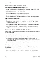
7. Set up System Variables? 


System Capture Rate: 0.25 – .5 – .75 – 1 – 2 – 3 – 4 – 5 – 6 – 7 – 8  


DVR Shutdown Delay: 00 minutes to 50 minutes. ____________ 


Audio Enable: Yes – No  


Minimum Storage Time for Surveillance: 1 – day to 9 – days. ____________ 


Minimum Storage Time for Alarms: 90 days to 10 days. ____________ 


Auto Adjust for Daylight-Saving Time: Yes – No


8. Set Up Vehicle Variables? 


Enter Vehicle ID:  ____________ 

 Vehicle 

Password: 

____________ 


DVR IP Address: ___.___.___.___


9. Set Up DVR Date & Time?

  Yes – No   


Notes:


Содержание MobileView

Страница 1: ...MobileView Mobile Digital Video Recorder ...

Страница 2: ...or otherwise incurred as a consequence directly or indirectly of the use or application of any of the contents of this document For the latest product specifications visit GE Interlogix Kalatel division online at www kalatel com or contact your GE Interlogix Kalatel division sales representative For technical support before and after installation call 800 469 1676 Technical support is available 24...

Страница 3: ...3 Adjusting Cameras for Functional Field of View 13 2 5 INSTALLING THE STATUS KEYPAD 15 2 6 INSTALLING THE IMPACT SENSOR OPTIONAL 16 2 7 INSTALLING THE PANIC BUTTON OPTIONAL 17 2 8 INSTALLING THE MICROPHONE OPTIONAL 17 3 DVR INSTALLATION AND WIRING 18 3 1 MOUNTING THE DVR HOUSING 18 3 2 WIRING THE DVR 19 3 2 1 Accessing the DVR Back Box 19 3 2 2 Camera and Keypad Wiring 20 3 2 3 Alarm and Trigger ...

Страница 4: ... Variable Setup Menus 33 5 1 5 Set Up Vehicle Variables 34 5 1 6 Set DVR Date and Time Menu 35 5 2 TRANSFER DATA MENUS 35 5 2 1 Copying Data From a Vehicle 35 5 2 2 Transferring Data To a Vehicle 36 5 3 EXITING KEYPAD MENUS 36 6 TROUBLESHOOTING 37 APPENDIX A MOUNTING PLATE TEMPLATE 43 APPENDIX B STATUS KEYPAD CONFIGURATION 45 APPENDIX C INSTALLATION CHECK SHEET 46 APPENDIX D DVR CONFIGURATION WORK...

Страница 5: ... and troubleshooting this product refer to this document and any other documentation provided If you still have questions please contact GE Interlogix Kalatel division Technical Support and Sales Kalatel a division of GE Interlogix Inc Call 800 469 1676 Fax 541 752 9096 Note you should be at the equipment and ready with details before calling Technical Support Conventions Used in this Manual Boldf...

Страница 6: ...en for a user designated period of time the default setting is 30 days or can be protected from being over written at all By using an optional modem MobileView can transmit images from the DVR to a central monitoring station through a cellular telephone network The cellular transmission is bidirectional so image transmission can be activated from the vehicle or central station 1 2 VIEWING AND RETR...

Страница 7: ...onsists of the required equipment and the accessories shown in Figure 1 Aluminum housing Keypad Microphone Camera DVRT antenna Panic Button Up to eight cameras per system DVRT antenna cable Impact Sensor RG179 Siamese coaxial cable Sierra Wireless modem DVR assembly Modem com RS232 cable Figure 1 Features of a MobileView system ...

Страница 8: ... are noted in the appropriate sections of the manual 2 1 TOOLS NECESSARY FOR INSTALLATION MobileView Test Kit Laptop viewing station Electrical volt meter BNC crimper Molex pin crimper Riv nut gun Socket set up to 5 8 in Wrenches up to 5 8 in Phillips and flathead screwdrivers Solder gun with solder Wire strippers Drill Drill bits up to 5 8 in Hole saws up to 1 1 8 in Locktite blue Torx bit secure...

Страница 9: ...us over the driver s head looking at the front passenger entry The Center to Rear camera is located between the front and rear door looking down the center aisle to the rear of the bus The Front to Rear camera is located in the front of the bus looking down the center aisle to the rear of the bus The Rear Exit camera is located across from the rear door looking at the rear doorway The Rear to Fron...

Страница 10: ...walls of the vehicle if possible insert grommets in the holes to protect the cable If it is not possible make sure that the protective outer CL2 jacket is maintained when passing the cable through the hole When pulling cable through the conduit do not jerk or over pull the cables These actions will stretch and damage the cable Attach a pull line to the cable jacket not to the connectors 1 Route ca...

Страница 11: ...ppendix A to mark the location of the cable entry hole and two mounting holes See Figure 4 2 Using a 3 16 inch 5 mm drill bit drill the two mounting holes 3 Using a 1 inch 25 4 mm drill bit drill the cable entry hole 4 Install a 3 4 inch 20 mm interior diameter grommet on the cable entry hole or where feasible 5 Connect the video and power cables to the camera and feed the excess cable into the ve...

Страница 12: ...5 inch 83 by 83 mm hole in the appropriate location on the mounting surface 3 Using the housing as a template mark the location of the mounting holes 4 Using a 3 16 inch 5 mm drill bit drill the mounting holes 5 Connect the video and power cables to the camera assembly 6 Mount the camera assembly to the vehicle surface using two fasteners screwed into panel nuts See Figure 7 or 8 depending on the ...

Страница 13: ...gle of the camera see Figure 11 and perform the following 1 Loosen the camera s pivot screws 2 Rotate the camera to the correct angle 3 Retighten the pivot screws Surface mount cameras are configured at the factory to be installed onto the ceiling of the vehicle If you are installing a surface mount camera on the side of the vehicle see Figure 12 and perform the following to rotate the camera lens...

Страница 14: ...ioned at the top of the camera 2 For cameras mounted on the street side of the bus or surface mounted facing backward remove the two side set screws as shown in Figure 14 and lift the camera out of its bracket 3 Rotate the entire camera assembly 180º See Figure 14 4 Insert the camera into the bracket and replace the set screws The lens set screw and the wiring harness should be positioned at the b...

Страница 15: ...gure 16 2 Drill the mounting holes 3 Mount the keypad 4 Run a four conductor 18 AWG twisted pair cable with overall shield from the keypad location to the DVR location 5 Trim the cable to the desired length 6 At the keypad end use a Molex crimper to crimp the wire s pins 7 Insert the wires into the receptacle end of the four pin Molex connector according to Figure 17 8 Plug the Molex connector int...

Страница 16: ...ect to vibrations 1 Using the Impact Sensor as a template mark the location of the two mounting holes The Impact Sensor should be aligned so that it is square with the front and rear of the vehicle See Figure 18 2 Drill the mounting holes with an appropriate size drill bit 3 Mount the Impact Sensor 4 Route the provided cable to the DVR Connections to the J11 terminal block on the DVR back box are ...

Страница 17: ...hangeable 5 Route the cable to the DVR Connections to the J11 terminal of the DVR back box are as follows N C and common 2 wires both yellow to terminals 3 and 4 normal wire green to terminal 13 check wire red to terminal 15 positive wire gray to terminal 18 negative wire white present only on the panic button with key reset to terminal 17 6 Mount the panic button 2 8 INSTALLING THE MICROPHONE OPT...

Страница 18: ... the door and to remove the DVR See Figure 23 and perform the following 1 Remove the four acorn nuts and locking washers from the top of the DVR outer housing 2 Remove the DVR housing Do not remove the vibration isolators or the bolts and nuts holding them in place 3 Mount the mounting plate to the vehicle using four nuts and bolts not provided 1 4 20 inch bolts are recommended Use the provided 1 ...

Страница 19: ... back box s two cover screws 2 Remove the back box from the DVR 3 Remove the splashguard by unscrewing the two screws inside the connection box Camera and keypad outputs J9 terminal block Four pin Molex J3 power management board BNC connectors video inputs J1 J8 EM shutdown resistor Modem port J10 serial port S1 switch Ethernet connector optional S2 switch Ferrite clamp on 4 conductor power cable ...

Страница 20: ...d 1 Remove the J9 terminal block in Figure 24 from the back box by loosening its mounting screws and pulling it out of its socket 2 Make connections as shown in Figure 26 To make connections strip each wire 3 8 inch 9 5 mm insert it into the appropriate slot and tighten the terminal screw 3 Reinstall the J9 terminal block Power 1 Power 5 Keypad power Power 2 Power 6 Keypad RS485 communication Powe...

Страница 21: ...k box by loosening its mounting screws and pulling it out of its socket 2 Strip each wire 3 8 inch 9 5 mm 3 Connect each trigger device as shown in Figure 28 each trigger device must have a normally closed connection with the DVR Note Terminal 18 also can be used for a panic button or an impact sensor up to three wires can go into terminal 18 3 2 3 1 IMPACT SENSOR CONNECTIONS The Impact Sensor s N...

Страница 22: ...s outputs on the J11 terminal block for optional use The most common uses for these outputs are as interfaces to a vehicle relay system or lights To communicate with a vehicle relay system contact the vehicle manufacturer To connect the status lights on the Panic Button to the status outputs see Figure 31 and perform the following 1 Connect the normal wire green to terminal 13 2 Connect the check ...

Страница 23: ...wer source to the DVR location 2 Make connections to the vehicle source contact the vehicle manufacturer for information on connecting to the vehicle power source 3 Crimp the wire pins using a Molex crimper and make connections to the DVR s four pin Molex according to Figure 33 4 Test the four pin Molex wire harness for power both continuous 24 VDC and engine running ignition Note For a working de...

Страница 24: ...re and that all terminal boards are securely fastened to the back box 1 25 inch 32 mm connectors can be used 2 Reconnect the splashguard to the back box following the contour of the wiring See Figure 25 3 Reconnect the back box to the DVR outer housing see Figure 22 or go to section 4 Testing Connections and reinstall the connection box when testing is complete ...

Страница 25: ...ates skip to step 8 If the LED does not illuminate proceed to step 6 6 If the green LED on the interface does not illuminate unplug the four pin Molex power connection on the DVR and plug it into the receptacle end of the interface cable and Power 24 VDC must be supplied to the DVR Add a ferrite clamp to the 24 V power cable at the Molex connector J3 7 Plug the interface cable Molex connectors int...

Страница 26: ...ch system can have a different number of inputs Be sure to test the connections to each of the inputs in your system If your system does not include any inputs skip this section and proceed to section 4 2 3 DVR Status 1 At the Test DVR display Figure 37 press the key to advance to the second Test DVR display Figure 38 2 Press the key to advance to the Current Status menu Figure 39 which shows the ...

Страница 27: ...om the Current Status menu Figure 41 press to proceed to the Test Outputs menu Figure 42 2 Press to test output 2 Figure 43 If a status light is connected to output 2 the light illuminates 3 Press again to test output 1 Figure 44 If a status light is connected to output 1 the light illuminates 4 Press again to test both outputs Figure 45 Both lights illuminates 4 2 3 DVR STATUS 1 To display the st...

Страница 28: ...f the camera in the system For example whichever camera is plugged into the DVR s BNC port 1 will be displayed as camera 1 on the keypad 4 Adjust and set the field of view for each camera section 2 4 3 Adjusting Cameras for Functional Field of View Focus the camera if necessary 5 After viewing and adjusting all cameras in the system scroll back with the key to the first Select Camera display Figur...

Страница 29: ...move from space to space when inputting data Use the keys to scroll through alphanumeric characters and symbols Note To alter the contrast of the keypad LCD display window simultaneously press the keys and while pressing those keys use the keys to adjust the contrast 5 1 SYSTEM CONFIGURATION Note If you are using the onboard status keypad skip step 1 1 Press the POWER button located below the Test...

Страница 30: ...cture Quality menu Figure 59 Note The capture rate programming feature of any camera in the system depends on the capture rate of the other cameras Therefore if you want camera 1 to capture images at a faster rate than other cameras in the system you must set camera 1 s capture rate to fast and the other cameras capture rates to normal or slow 5 Select the picture quality by pressing the keys You ...

Страница 31: ...er an input is an alarm is a trigger or is disabled Press the key to advance to the Input Name menu Figure 64 Note An input designated as an alarm will tag images create an event file for images notify for transmission if enabled increase the capture rate to fast and increase the resolution to high An input designated as a trigger does not tag images but can be used to program a change in resoluti...

Страница 32: ...u want the input to notify when there is an alarm If you select this option the modem will dial the central station when the alarm is activated Press the key to return to the Select Input menu Figure 62 8 In the Select Input menu use the keys to select the next input 9 When you have finished configuring inputs use the keys in the Select Input menu to return the selection to none and press the key ...

Страница 33: ...f you are programming a MobileView III system the capture rate capabilities are tripled However to ensure the keypad s backward compatibility the fps rates on the System Capture Rate menu Figure 71 are still listed at between 0 25 and 8 fps See Table 1 to set the capture rate for a MobileView III system CENTRAL IP ADDRESS ___ ___ ___ ___ NEXT SUBNET MASK 255 255 000 000 NEXT Figure 69 Setup Transm...

Страница 34: ...d frames per second 7 Use the keys to enter the minimum number of days 0 90 that images tagged from alarms will be protected from being overwritten Press the key to advance to the Daylight Savings menu Figure 76 Note When the DVR is unable to comply with the minimum you enter you will be notified by a red light on the Panic Button s status output if a Panic Button is used 8 If you want the DVR to ...

Страница 35: ...ect yes Use the keys to select the alphanumeric characters and the keys to move from character to character Press the key to advance to the Transfer Data menu Figure 82 5 2 TRANSFER DATA MENUS If you are using a Test Kit to configure the DVR the configuration information that you enter for one vehicle can be stored and transferred to other vehicles If you are copying data from a vehicle see sectio...

Страница 36: ...rite menu Figure 86 if transferring All Data Figure 87 if transferring Fleet Data 3 The Rewrite menu offers a safety check it will ask you if you are sure you want to transfer the data you have selected Use the keys to select yes or no Press the key to advance to the next menu If you selected yes you will be taken to the Exit menu Figure 88 If you selected no you will be returned to the Transfer D...

Страница 37: ...e left button increases volume and the right button decreases volume Audio settings will be displayed on the keypad OPTIONAL STATUS LIGHTS The status lights will alert you to the status of the DVR DVR status lights should not be confused with DVR LEDs The LEDs are located on the front of the removable DVR unit The term status lights is used to refer to any lights or LEDs connected to the two outpu...

Страница 38: ...S NOT START UP WITH VEHICLE IGNITION If 24 VDC continuous power is present but the DVR does not start up with vehicle running no fans can be heard running in the box use the keypad to verify DVR status The keypad will display the MobileView menu Figure 90 1 Enter test mode by using the access password of the keypad 2 Press the key to select yes at the Test DVR display Figure 54 3 Press the key thr...

Страница 39: ...e to run after the vehicle has been turned off see section 5 1 4 System Variable Setup Menus The status lights are supplied with 12 or 30 VDC continuous power from the vehicle Verify that continuous voltage is present at the status light The ground for the status lights is supplied by the DVR connection box To check the ground output with a voltage meter perform the following 1 Place the positive ...

Страница 40: ...e the jumper and meter one end of the disconnected coaxial cable There should be no resistance VIDEO IS PRESENT AT TEST BUT IS NOT CAPTURED IN THE SURVEILLANCE DATABASE Using the LCD keypad check the setup of the camera port Be sure that the camera has been enabled in the Camera Setup menus NO DISPLAY ON THE LCD KEYPAD 1 Verify that the DVR has 24 VDC continuous power at the four pin Molex connect...

Страница 41: ...r exits the keypad program the DVR will restart and begin using the new configuration Depending on the amount of changes this may take several minutes 1 If configuration changes were made while in test mode start up the DVR and wait until it is capturing images 2 Reenter the keypad password to enter configuration mode 3 Make any necessary changes in the configuration 4 Exit keypad configuration mo...

Страница 42: ...42 1036564B October 2002 ...

Страница 43: ...MobileView User Manual Appendix A Mounting Plate Template 1036564B October 2002 43 APPENDIX A MOUNTING PLATE TEMPLATE All measurements shown in inches ...

Страница 44: ...44 1036564B October 2002 ...

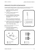
Страница 45: ...ull off the jumper and move it down one pin See Figure B3 Note The keypad voltage setting J2 jumper assembly must match the S1 switch setting inside the DVR on the back box i e it must be 5 VDC in both places or 12 VDC in both places 4 All keypads should be set as slave switches 1 3 on switch 4 off If you want to set the keypad as master all four switches must be in the on position in order to ena...

Страница 46: ... cable TNC PL 259 Modem power present Modem DB9 cable secure SAS N C input Impact Sensor input Normal status negative output Check status negative output Camera cables 1 8 Camera cable BNCs 1 8 Camera 1 field of view Camera 2 field of view Camera 3 field of view Camera 4 field of view Camera 5 field of view Camera 6 field of view Camera 7 field of view Camera 8 field of view System enclosure secur...

Страница 47: ...rigger Picture Quality High Medium Low Camera 4 Color B W Disable Camera Name ________________ Capture Rate Fast Slow Normal Picture Quality High Medium Low Camera 4 Trigger Capture Rate Fast Slow Normal Camera 4 Trigger Picture Quality High Medium Low Camera 5 Color B W Disable Camera Name ________________ Capture Rate Fast Slow Normal Picture Quality High Medium Low Camera 5 Trigger Capture Rate...

Страница 48: ...minutes ____________ Input 4 Post Alarm Time 00 seconds to 10 minutes ____________ Input 5 Type Alarm Trigger Disabled Input 5 Name ____________ Input 5 Pre Alarm Time 00 seconds to 10 minutes ____________ Input 5 Post Alarm Time 00 seconds to 10 minutes ____________ Input 6 Type Alarm Trigger Disabled Input 6 Name ____________ Input 6 Pre Alarm Time 00 seconds to 10 minutes ____________ Input 6 P...

Страница 49: ...minutes to 50 minutes ____________ Audio Enable Yes No Minimum Storage Time for Surveillance 1 day to 9 days ____________ Minimum Storage Time for Alarms 90 days to 10 days ____________ Auto Adjust for Daylight Saving Time Yes No 8 Set Up Vehicle Variables Enter Vehicle ID ____________ Vehicle Password ____________ DVR IP Address ___ ___ ___ ___ 9 Set Up DVR Date Time Yes No Notes ...

Страница 50: ...50 1036564B October 2002 ...

Страница 51: ...parts labor and shipping Labor will be billed in half hour increments Before shipping the product s to GE Interlogix Kalatel division back up the data stored on the hard disk drive s and any other storage device s in the product s Remove any media such as disks and CDs GE Interlogix Kalatel division does not accept liability for lost data or software Note Customers requesting an estimate prior to ...

Страница 52: ......

Отзывы: