


3 DVR Installation and Wiring
MobileView User Manual
20
1036564B / October 2002
3.2.2 C
AMERA AND
K
EYPAD
W
IRING
Note:
If you are installing the keypad more than 100 feet (30 m) from the DVR, set the S1 switch (
in Figure 24) to the down
position. If you are installing eight cameras (system maximum), set the S2 switch (
in Figure 24) to the down position.
CAUTION
Do not confuse the J9 terminal block with the J11 terminal block. The J9 is above the J11 and is for
camera and keypad connections; the J11 is for input/output wiring.
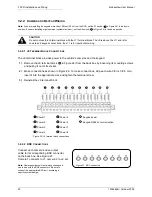
3.2.2.1 J9 T
ERMINAL
B
LOCK
C
ONNECTIONS
The J9 terminal block provides power to the vehicle’s cameras and the keypad.
1)
Remove the J9 terminal block (
in Figure 24) from the back box by loosening its mounting screws
and pulling it out of its socket.
2)
Make connections as shown in Figure 26. To make connections, strip each wire 3/8 inch (9.5 mm),
insert it into the appropriate slot, and tighten the terminal screw.
3)
Reinstall the J9 terminal block.
Power 1
Power 5
Keypad power
Power 2
Power 6
Keypad RS485 communication
Power 3
Power 7
Power 4
Power 8
Figure 26. J9 terminal block connections
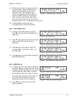
3.2.2.2 BNC C
ONNECTIONS
Connect each camera’s video output
cable to its corresponding BNC connector
on the back box. See Figure 27.
Camera 1 connects to J1, camera 2 to J2, etc.
Note:
Camera numbers will not always correspond
one to one with the BNC connectors. Be sure to
connect the appropriate BNC port, according to
specific system design.
Figure 27. BNC connectors
Содержание MobileView
Страница 1: ...MobileView Mobile Digital Video Recorder ...
Страница 42: ...42 1036564B October 2002 ...
Страница 44: ...44 1036564B October 2002 ...
Страница 50: ...50 1036564B October 2002 ...
Страница 52: ......


