


CHAPTER 5: SETPOINTS
S7 TESTING
MM3 MOTOR MANAGER 3 – INSTRUCTION MANUAL
5–39
While the
OPERATION TEST
setpoint is displayed, use the VALUE keys to scroll to the desired
output relay and/or status indicator to be tested. As long as the test message remains
displayed the respective output relay and/or status indicator will be forced to remain
energized. As soon as a new message is selected, the respective output relay and/or status
indicator return to normal operation.
As a safeguard, relay and LED test will turn off automatically if:
• power to the MM3 Motor Manager 3 is turned off and on
• the
RELAYS & LEDS SIMULATION
setpoint is OFF
• any trips are present
• phase or ground current is detected by the MM3 Motor Manager 3
• new message is displayed
5.8.3
Current
Simulation
PATH: S7 TESTING
ÖØ
CURRENT SIMULATION
Simulated currents can be forced instead of the actual currents sensed by the MM3 Motor
Manager 3 CTs. This allows verification of all current related relay functions such as timed
overload trip. It also allows verification that external trip and alarm wiring is responding
correctly.
The current simulation settings are programmed as follows:
•
SIMULATION
: Enter the required simulation phase and ground currents in the
following messages. Select “ON” to switch from actual currents to the programmed
simulated values. This command is ignored if real phase or ground current is present.
Select “OFF” after simulation is complete. As a safeguard, simulation will automatically
turn off if:
• real phase or ground current is detected while in simulation mode
• power to the MM3 Motor Manager 3 is turned off and on
• the
SIMULATION ENABLED FOR
time has elapsed since simulation was first enabled
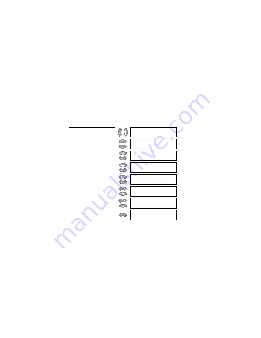
] CURRENT SIMULATION
]
SIMULATION:
OFF
Range: ON, OFF
SIMULATION ENABLED
FOR:
15 min.
Range: 5 to 300 min. or UNLIMITED in
steps of 5
PHASE A CURRENT
0 A
Range: 0 to 10000 A in steps of 1
PHASE B CURRENT
0 A
Range: 0 to 10000 A in steps of 1
PHASE C CURRENT
0 A
Range: 0 to 10000 A in steps of 1
GROUND CURRENT:
0 A
Range: 0 to 500.0 A in steps of 0.1
VOLTAGE:
0 V
Range: 0 to 3000 V in steps of 1
POWER:
0 kW
Range: 0 to 359 kW in steps of 1
Содержание MM3
Страница 8: ...vi MM3 MOTOR MANAGER 3 INSTRUCTION MANUAL TABLE OF CONTENTS ...
Страница 11: ...CHAPTER 1 INTRODUCTION OVERVIEW MM3 MOTOR MANAGER 3 INSTRUCTION MANUAL 1 3 Figure 1 1 Functional block diagram ...
Страница 18: ...1 10 MM3 MOTOR MANAGER 3 INSTRUCTION MANUAL TECHNICAL SPECIFICATIONS CHAPTER 1 INTRODUCTION ...
Страница 80: ...4 18 MM3 MOTOR MANAGER 3 INSTRUCTION MANUAL CHASSIS MOUNT UNITS CHAPTER 4 SOFTWARE ...
Страница 124: ...5 44 MM3 MOTOR MANAGER 3 INSTRUCTION MANUAL S7 TESTING CHAPTER 5 SETPOINTS ...
Страница 198: ...8 54 MM3 MOTOR MANAGER 3 INSTRUCTION MANUAL MODBUS MEMORY MAP CHAPTER 8 COMMUNICATIONS ...
Страница 220: ...10 14 MM3 MOTOR MANAGER 3 INSTRUCTION MANUAL GE MULTILIN WARRANTY CHAPTER 10 MISCELLANEOUS ...