background image

GE 
Direction 5370626-100, Revision 18                          LOGIQ e/LOGIQ e Vet/LOGIQ i/Vivid  e Basic Service Manual

Chapter 3 System Setup

3-19

3-6-5-3

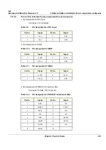
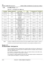
This section indicates the pin assignment for each connector.

1. Pin Assignment of DC input

Connector: 4 Pin, Female

Table 3-9

   Pin Assignments of DC input

2. Pin Assignment of USB

Table 3-10    Pin assignment of USB1

Table 3-11    Pin assignment of USB2

3. Pin assignment of RS232C for external VGA

Connector: D-SUB, 15Pin, Female

Table 3-12    Pin Assignments of RS232C for External VGA

Pin No.

Signal

Pin No.

Signal

1

+20V

3

GND

2

+20V

4

GND

Pin No.

Signal

Pin No.

Signal

1

+5VDC

3

DATA+

2

DATA-

4

GND

Pin No.

Signal

Pin No.

Signal

1

+5VDC

3

DATA+

2

DATA-

4

GND

Pin No.

Signal

Pin No.

Signal

1

RED

9

N/A

2

GREEN

10

SGND

3

BLUE

11

N/A

4

N/A

12

N/A

5

GND

13

HSYNC

6

RGND

14

VSYNC

7

GGND

15

N/A

8

BGND

16

Содержание 5151219

Страница 1: ...GE LOGIQ e LOGIQ e Vet LOGIQ i Vivid e Basic Service Manual Part Number 5370626 100 Revision 18 ...

Страница 2: ...This manual covers the software versions for the products as below LOGIQ e R4 x x R5 x x R6 x x R7 x x LOGIQ e Vet R5 x x R6 x x R7 x x VIVID e R4 x x R5 x x R6 x x LOGIQ i R4 x x R5 x x ...

Страница 3: ...UE L ANGLAIS C EST AU CLIENT QU IL INCOMBE DE LE FAIRE TRADUIRE NE PAS TENTER D INTERVENTION SUR LES éQUIPEMENTS TANT QUE LE MANUEL SERVICE N A PAS éTé CONSULTé ET COMPRIS LE NON RESPECT DE CET AVERTISSEMENT PEUT ENTRAîNER CHEZ LE TECHNICIEN L OPéRATEUR OU LE PATIENT DES BLESSURES DUES à DES DANGERS éLECTRIQUES MéCANIQUES OU AUTRES DIESES KUNDENDIENST HANDBUCH EXISTIERT NUR IN ENGLISCHER SPRACHE F...

Страница 4: ...ERADOR OU PACIENTE DEVIDO A CHOQUES ELéTRICOS MECâ NICOS OU OUTROS ESTE MANUAL DE ASSISTÊNCIA ESTÁ DISPONÍVEL APENAS EM INGLÊS SE QUALQUER OUTRO SERVIÇO DE ASSISTÊNCIA TÉCNICA QUE NÃO A GEHC SOLICITAR ESTES MANUAIS NOUTRO IDIOMA É DA RESPONSABILIDADE DO CLIENTE FORNECER OS SERVIÇOS DE TRADUÇÃO NÃO TENTE EFECTUAR REPARAÇÕES NO EQUIPAMENTO SEM TER CONSULTADO E COMPREENDIDO PREVIAMENTE ESTE MANUAL A ...

Страница 5: ...Kä YTTä Jä N TAI POTILAAN VAHINGOITTUMINEN Sä HKö ISKUN MEKAANISEN VIAN TAI MUUN VAARATILANTEEN VUOKSI ΤΟ ΠΑΡΟΝ ΕΓΧΕΙΡΙ ΙΟ ΣΕΡΒΙΣ ΙΑΤΙΘΕΤΑΙ ΣΤΑ ΑΓΓΛΙΚΑ ΜΟΝΟ ΕΑΝ ΤΟ ΑΤΟΜΟ ΠΑΡΟΧΗΣ ΣΕΡΒΙΣ ΕΝΟΣ ΠΕΛΑΤΗ ΑΠΑΙΤΕΙ ΤΟ ΠΑΡΟΝ ΕΓΧΕΙΡΙ ΙΟ ΣΕ ΓΛΩΣΣΑ ΕΚΤΟΣ ΤΩΝ ΑΓΓΛΙΚΩΝ ΑΠΟΤΕΛΕΙ ΕΥΘΥΝΗ ΤΟΥ ΠΕΛΑΤΗ ΝΑ ΠΑΡΕΧΕΙ ΥΠΗΡΕΣΙΕΣ ΜΕΤΑΦΡΑΣΗΣ ΜΗΝ ΕΠΙΧΕΙΡΗΣΕΤΕ ΤΗΝ ΕΚΤΕΛΕΣΗ ΕΡΓΑΣΙΩΝ ΣΕΡΒΙΣ ΣΤΟΝ ΕΞΟΠΛΙΣΜΟ ΕΚΤΟΣ ΕΑΝ ΕΧΕΤΕ ΣΥΜΒΟΥΛΕΥΤ...

Страница 6: ... PRACOVNíKA POSKYTOVATELE SLUŽEB OBSLUŽNéHO PERSONá LU NEBO PACIENTů VLIVEM ELEKTRICKéHOP PROUDU RESPEKTIVE VLIVEM K RIZIKU MECHANICKÉHO POŠKOZENÍ NEBO JINÉMU RIZIKU DENNE SERVICEMANUAL FINDES KUN PÅ ENGELSK HVIS EN KUNDES TEKNIKER HAR BRUG FOR ET ANDET SPROG END ENGELSK ER DET KUNDENS ANSVAR AT SØRGE FOR OVERSÆTTELSE FORSØG IKKE AT SERVICERE UDSTYRET MEDMINDRE DENNE SERVICEMANUAL ER BLEVET LÆST O...

Страница 7: ...ENTAS GALI BŪTI SUŽEISTAS DĖL ELEKTROS SMŪGIO MECHANINIŲ AR KITŲ PAVOJŲ DENNE SERVICEHÅNDBOKEN FINNES BARE PÅ ENGELSK HVIS KUNDENS SERVICELEVERANDØR TRENGER ET ANNET SPRÅK ER DET KUNDENS ANSVAR Å SØRGE FOR OVERSETTELSE IKKE FORSØK Å REPARERE UTSTYRET UTEN AT DENNE SERVICEHÅNDBOKEN ER LEST OG FORSTÅTT MANGLENDE HENSYN TIL DENNE ADVARSELEN KAN FØRE TIL AT SERVICELEVERANDØREN OPERATØREN ELLER PASIENT...

Страница 8: ...ИЙ МОЖЕТ ПРИВЕСТИ К ТОМУ ЧТО СПЕЦИАЛИСТ ПО ТЕХОБСЛУЖИВАНИЮ ОПЕРАТОР ИЛИ ПАЦИЕНТ ПОЛУЧАТ УДАР ЗЛЕКТРИЧЕСКИМ ТОКОМ МЕХАНИЧЕСКУЮ ТРАВМУ ИЛИ ДРУГОЕ ПОВРЕЖДЕНИЕ ТОВА СЕРВИЗНО РЪКОВОДСТВО Е НАЛИЧНО САМО НА АНГЛИЙСКИ ЕЗИК АКО ДОСТАВЧИКЪТ НА СЕРВИЗНИ УСЛУГИ НА КЛИЕНТ СЕ НУЖДАЕ ОТ ЕЗИК РАЗЛИЧЕН ОТ АНГЛИЙСКИ ЗАДЪЛЖЕНИЕ НА КЛИЕНТА Е ДА ПРЕДОСТАВИ ПРЕВОДАЧЕСКА УСЛУГА НЕ СЕ ОПИТВАЙТЕ ДА ИЗВЪРШВАТЕ СЕРВИЗНО ОБС...

Страница 9: ...CIJENTA PROUZROČENE STRUJNIM UDAROM MEHANIČKIM I DRUGIM OPASNOSTIMA TÁTO SERVISNÁ PRÍRUČKA JE K DISPOZíCII LEN V ANGLIČTINE AK ZÁKAZNÍKOV POSKYTOVATEĽ SLUŽIEB VYŽADUJE INÝ JAZYK AKO ANGLIČTINU POSKYTNUTIE PREKLADATEĽSKÝCH SLUŽIEB JE ZODPOVEDNOSŤOU ZÁKAZNÍKA NEPOKÚŠAJTE SA VYKONÁVAŤ SERVIS ZARIADENIA SKÔR AKO SI NEPREČÍTATE SERVISNÚ PRÍRUČKU A NEPOROZUMIETE JEJ ZANEDBANIE TOHTO UPOZORNENIA Mô ŽE VY...

Страница 10: ...YENİ KILAVUZUN İNGİLİZCE DIŞINDAKİ BİR DİLDE OLMASINI İSTERSE KILAVUZU TERCÜME ETTİRMEK MÜŞTERİNİN SORUMLULUĞUNDADIR SERVİS KILAVUZUNU OKUYUP ANLAMADAN EKİPMANLARA MÜDAHALE ETMEYİNİZ BU UYARININ GÖZ ARDI EDİLMESİ ELEKTRİK ÇARPMASI YA DA MEKANİK VEYA DİĞER TÜRDEN KAZALAR SONUCUNDA TEKNİSYENİN OPERATÖRÜN YA DA HASTANIN YARALANMASINA YOL AÇABİLİR DİKKAT TR JA Traditional Chinese ...

Страница 11: ...GE Direction 5370626 100 Revision 18 LOGIQ e LOGIQ e Vet LOGIQ i Vivid e Basic Service Manual ix ZH CN KO ...

Страница 12: ...s will comply with the requirements of the applicable electrical codes The purchaser of GE equipment shall only utilize qualified personnel i e GE s field engineers personnel of third party service companies with equivalent training or licensed electricians to perform electrical servicing on the equipment OMISSIONS ERRORS If there are any omissions errors or suggestions for improving this document...

Страница 13: ... duplicated in any form in whole or in part without prior written permission of GE Healthcare GE Healthcare may revise this publication from time to time without written notice TRADEMARKS All products and their name brands are trademarks of their respective holders COPYRIGHTS All Material Copyright 2004 to 2016 by General Electric Company Inc All Rights Reserved ...

Страница 14: ... 2012 Add instruction for Loading the System Software with USB Memory Stick 10 10 Dec 2012 Update Chapter 9 about spare parts 11 17 Dec 2012 Update package label and add new spare parts 12 23 Jan 2013 Update for LOGIQ e Vet R7 x x 13 08 Aug 2013 Add notes in Chapter 8 14 17 April 2014 Update Bookbinding method 15 29 May 2014 Update spare part list 16 28 Feb 2015 Update spare part list 17 30 June 2...

Страница 15: ... 1 6 Important Conventions 1 7 Conventions Used in Book 1 7 Standard Hazard Icons 1 8 Product Icons 1 9 Safety Considerations 1 13 Introduction 1 13 Human Safety 1 13 Mechanical Safety 1 13 Electrical Safety 1 13 Label Location 1 13 Battery Safety 1 14 Dangerous Procedure Warnings 1 15 Lockout Tagout LOTO requirements 1 15 Returning Shipping Probes and Repair Parts 1 16 EMC EMI and ESD 1 17 Electr...

Страница 16: ...rpose of this chapter 2 2 1 Chapter Contents 2 1 General Console Requirements 2 2 Console Environmental Requirements 2 2 Electrical Requirements 2 2 EMI Limitations 2 4 Scan Probe Environmental Requirements 2 5 Facility Needs 2 6 Recommended Ultrasound Room Layout 2 6 Required Features 2 7 Desirable Features 2 7 Networking Pre installation Requirements 2 9 ...

Страница 17: ... Order 3 8 Physical Inspection 3 8 EMI Protection 3 8 Completing the Installation 3 9 Power On Boot Up 3 9 Power Off Shutdown 3 10 Transducer Connection 3 11 System Configuration 3 12 System Specifications 3 12 Electrical Specifications 3 14 Approved peripherals 3 15 Connecting Cables 3 17 Peripherals Accessories Connector Panel 3 17 Available Probes 3 28 Software Option Configuration 3 30 Connect...

Страница 18: ...n 4 3 Archiving and Loading Presets 4 5 Adjusting the Display Monitor 4 6 Lockout Tagout LOTO requirements 4 6 System Features 4 7 B Mode Checks 4 10 M Mode Controls 4 13 Color Flow Mode Checks 4 16 Doppler Mode Checks 4 20 CWD Functional Check 4 24 Basic Measurements 4 25 Probe Connectors Usage 4 25 Using Cine 4 26 Image Management QG 4 27 Backup and Restore Database Preset Configurations and Ima...

Страница 19: ...5 2 General Information 5 3 External I O 5 4 Peripherals 5 4 Wiring 5 5 Power Diagrams 5 6 Overview 5 6 AC Power 5 6 Battery charging 5 7 Air Flow Distribution 5 8 Fans 5 9 Common Service Platform 5 10 Introduction 5 10 Global Service User Interface GSUI 5 10 Service Home Page 5 12 Error Logs Tab 5 13 Diagnostics 5 17 Image Quality 5 18 Calibration 5 18 Configuration 5 19 Utilities 5 19 Replacemen...

Страница 20: ...26 100 Revision 18 LOGIQ e LOGIQ e Vet LOGIQ i Vivid e Basic Service Manual Table of Contents 6 CHAPTER 6 Service Adjustments Overview 6 1 Purpose of this chapter 6 6 1 Monitor Adjustments 6 2 Adjustments Procedures 6 2 ...

Страница 21: ...es 7 6 Check and Record the P1 Key Function 7 6 Setting the P1 Key to Screen Capture 7 6 Capturing a Screen 7 6 Reset the P1 Key to Customer s Functionality 7 8 Global Service User Interface GSUI 7 9 Enter global service user interface 7 9 Active Diagnostic Function 7 10 Control Frame 7 10 Common Diagnostics 7 12 Utilities 7 12 PC Diagnostics Non Interactive Tests 7 13 PC Diagnostics Interactive T...

Страница 22: ...Q e LOGIQ e Vet LOGIQ i Vivid e 8 1 Warning and Caution 8 1 Handle Assy FRU No 313 8 2 Loading the System Software 8 4 Loading Base Image Software with DVD 8 5 Loading the System Software with USB Memory Stick 8 10 Reload the Correct Preset Region 8 17 Option Strings Check 8 20 Probe Recognition Check 8 21 Peripheral Device Check 8 21 Reinstall DICOM Devices 8 22 Checks after FRU replacement Debri...

Страница 23: ...9 1 List of Abbreviations 9 1 Renewal Parts Lists 9 2 Equipment Models Covered in this Chapter 9 2 Operator Console Assy 9 3 LCD Assy 9 4 Keyboard Assy 9 7 Bottom Assy 9 11 Options of spare parts for LOGIQ e Vet Systems for USA 9 18 Cables 9 20 Isolation Cart Components 9 21 Isolation Cart Enhanced Version Components 9 23 Accessories and Kits 9 26 Manuals 9 35 Probe 9 40 ...

Страница 24: ...s be performed 10 3 Tools Required 10 4 Special Tools Supplies and Equipment 10 4 System Maintenance 10 5 Preliminary Checks 10 5 Functional Checks See Also Chapter 4 10 6 Input Power 10 7 Cleaning 10 7 Physical Inspection 10 8 Optional Diagnostic Checks 10 9 Probe Maintenance 10 9 Battery Performance Maintenance 10 10 Electrical Safety Tests 10 11 Safety Test Overview 10 11 GEMS Leakage Current L...

Страница 25: ...nctional checks that are recommended as part of the installation or as required during servicing and periodic maintenance 5 Chapter 5 Components and Functions Theory Contains block diagrams and functional explanations of the electronics 6 Chapter 6 Service Adjustments Contains instructions on how to make available adjustments to the LOGIQ e LOGIQ e Vet LOGIQ i Vivid e 7 Chapter 7 Diagnostics Troub...

Страница 26: ...LOGIQ e LOGIQ e Vet LOGIQ i Vivid e Basic Service Manual 1 2 1 1 4 Typical Users of the Basic Service Manual Service Personnel installation maintenance etc Hospital s Service Personnel Contractors Some parts of Chapter 2 Site Preparations ...

Страница 27: ...IQ e Vet R5 0 x Console for Europe 5198793 LOGIQ e LOGIQ e Vet R5 0 x Console for China 5198161 LOGIQ e LOGIQ e Vet R5 0 x Console for Japanese 5199693 LOGIQ e LOGIQ e Vet R5 0 x Console for Australia 5212841 LOGIQ e LOGIQ e Vet R5 0 x Console for India Table 1 4 LOGIQ e R5 2 x Model Designations Part Number Description 5323370 LOGIQ e R5 2 x Console for USA 5323375 LOGIQ e R5 2 xConsole for Argen...

Страница 28: ...x x Console for India 5432754 LOGIQ e R7 x x Console for Korea 5439035 LOGIQ e R7 x x Console for CKD USA 5447891 LOGIQ e R7 x x Console for China Table 1 7 LOGIQ i R4 x x Model Designations Part Number Description 5176830 LOGIQ i R4 1 x Console for USA 5179969 LOGIQ i R4 1 x Console for Argentina 5179685 LOGIQ i R4 1 x Console for Europe 5179209 LOGIQ i R4 1 x Console for China 5179748 LOGIQ i R4...

Страница 29: ...213329 Vivid e R5 x x Console for Japan 5212851 Vivid e R5 x x Console for Australia 5199644 Vivid e R5 x x Console for India South Africa 5183318 Vivid e R5 x x Console with SKD ECG for Europe 5435024 Vivid e R5 x x Console for USA 5435025 Vivid e R5 x x Console for Europe 5435026 Vivid e R5 x x Console for Argentina 5435027 Vivid e R5 x x Console for India 5435028 Vivid e R5 x x Console for Aust...

Страница 30: ...4 Vivid e R6 x x Console for EU 5435035 Vivid e R6 x x Console for Argentina 5435036 Vivid e R6 x x Console for India 5435037 Vivid e R6 x x Console for Australia 5435038 Vivid e R6 x x Console for Japan 5435040 Vivid e R6 x x Console for SKD ECG Table 1 12 LOGIQ e Vet R6 x x Model Designations Part Number Description 5198415 2 LOGIQ e Vet R6 x x Console for EU 5199518 2 LOGIQ e Vet R6 x x Console...

Страница 31: ...or potential hazards are labeled in one of following ways NOTE Notes provide important information about an item or a procedure Information contained in a NOTE can often save you time or effort DANGER DANGER IS USED TO INDICATE THE PRESENCE OF A HAZARD THAT WILL CAUSE SEVERE PERSONAL INJURY OR DEATH IF THE INSTRUCTIONS ARE IGNORED WARNING WARNING WARNING IS USED TO INDICATE THE PRESENCE OF A HAZAR...

Страница 32: ...pter In addition to text several different graphical icons symbols may be used to make you aware of specific types of hazards that could cause harm Other hazard icons make you aware of specific procedures that should be followed Table 1 14 Standard Hazard Icons ELECTRICAL MECHANICAL RADIATION LASER HEAT PINCH Table 1 15 Standard Icons Indicating a Special Procedure Be Used AVOID STATIC ELECTRICITY...

Страница 33: ...o indicate the degree of safety or protection Bottom panel of the adapter IP Code IPX1 or IPX8 IPX1 FSU 2001 IPX8 MKF 2 MED GP26 FSU 1000 Indicates the degree of protection provided by the enclosure per IEC60 529 IPX1 cannot be used in operating room environment IPX8 can be used in operating room environment Bottom of Footswitch Authorized European Representative address Bottom panel United States...

Страница 34: ...me and or logo of the testing laboratory product category safety standard is assessed and a control number Bottom panel of the console Date of manufacture The date could be a year year and month or year month and day as appropriate See ISO 8601 for date formates Rating Plate Catalog or model number Rating Plate Serial number Rating Plate Direct Current For products to be powered from a DC supply R...

Страница 35: ...r to automatically close Rating Plate Indicates the product contains hazardous materials in excess of the limits established by Chinese standard SJ T11363 2006 Requirements for Concentration Limits for Certain Hazardous Substances in Electronic Information Products The number in the symbol is the Environment friendly Use Period EFUP which indicates the period during which the toxic or hazardous su...

Страница 36: ...e battery may be safely removed from the device please consult the service manual or equipment instructions Information on the potential effects on the environment and human health of the substances used in batteries is available at this url http www gehealthcare com euen weee recycling index html Battery Pack No hazardous substance above the maximum concentration value is present Maximum concentr...

Страница 37: ... unpaved roads excessive speeds and erratic stops or starts 1 3 4 Electrical Safety To minimize shock hazard the equipment chassis must be connected to an electrical ground The system is equipped with a three conductor AC power cable This must be plugged into an approved electrical outlet with protective ground The power outlet used for this equipment should not be shared with other types of equip...

Страница 38: ...m the battery causing equipment damage observe the following precautions Do not immerse the battery in water or allow it to get wet Do not put the battery into a microwave oven or pressurized container If the battery leaks or emits an odor remove it from all possible flammable sources If the battery emits an odor or heat is deformed or discolored or in a way appears abnormal during use recharging ...

Страница 39: ... ARE PRESENT IN THIS EQUIPMENT USE EXTREME CAUTION WHEN HANDLING TESTING AND ADJUSTING WARNING WARNING EXPLOSION WARNING DO NOT OPERATE THE EQUIPMENT IN AN EXPLOSIVE ATMOSPHERE OPERATION OF ANY ELECTRICAL EQUIPMENT IN SUCH AN ENVIRONMENT CONSTITUTES A DEFINITE SAFETY HAZARD WARNING WARNING DO NOT SUBSTITUTE PARTS OR MODIFY EQUIPMENT BECAUSE OF THE DANGER OF INTRODUCING ADDITIONAL HAZARDS DO NOT IN...

Страница 40: ... or intended for use in patient care are regulated medical waste for transportation purposes and must be transported as a hazardous material NOTE The USER SERVICE staff should dispose all the waste properly as per federal state and local waste disposal regulation The ultrasound system is not meant to be long term storage of patient data or images The user is responsible for the date on the system ...

Страница 41: ...l cables In addition to electromagnetic energy EMC also includes possible effects from electrical fields magnetic fields electrostatic discharge and disturbances in the electrical power supply 1 4 2 CE Compliance The LOGIQ e LOGIQ e Vet LOGIQ i Vivid e unit conforms to all applicable conducted and radiated emission limits and to immunity from electrostatic discharge radiated and conducted RF field...

Страница 42: ... Ultrasound Service Engineering 9900 Innovation Drive Wauwatosa WI 53226 Service On site Service Parts Applications support 1 800 437 1171 1 800 558 2040 1 800 682 5327 or 1 262 524 5698 14470 Bergen Blvd Suite 400 Noblesville IN 46060 Inquires Loaner Return Depot PTL 317 814 8421 317 814 8409 Canada 1 800 668 0732 Latin America Service Applications support 1 800 321 7937 1 262 524 5698 Europe GE ...

Страница 43: ...28 TEL 86 510 85225888 FAX 86 510 85226688 Table 1 19 Factory Sites Manufacturer Phone Number GE Medical Systems China Co Ltd No 19 Changjiang Road Wuxi National Hi Tech Dev Zone Jiangsu P R China 214028 TEL 86 510 85225888 FAX 86 510 85226688 GE Ultrasound Korea 65 1 Sangdaewon dong Jungwon gu Seongnam si Gyeonggi do Korea 462 120 TEL 82 31 740 6112 FAX 82 31 740 6435 GE Medical Systems Ultrasoun...

Страница 44: ...GE Direction 5370626 100 Revision 18 LOGIQ e LOGIQ e Vet LOGIQ i Vivid e Basic Service Manual 1 20 Section 1 5 Customer Assistance This page was intentionally left blank ...

Страница 45: ...pter 2 This chapter provides the information required to plan and prepare for the installation of a LOGIQ e LOGIQ e Vet LOGIQ i Vivid e Included are descriptions of the facility and electrical needs to be met by the purchaser of the unit 2 1 2 Chapter Contents Table 2 1 Contents in Chapter 2 Section Description Page Number 2 1 Overview 2 1 2 2 General Console Requirements 2 2 2 3 Facility Needs 2 ...

Страница 46: ...ed line shall consist of one phase a neutral not shared with any other circuit and a full size ground wire from the distribution panel to the Ultrasound outlet Sites with a mains power system without a defined Neutral The dedicated line shall consist of one phase two lines not shared with any other circuit and a full size ground wire from the distribution panel to the Ultrasound outlet Please note...

Страница 47: ...test equipment needed to support this unit must also be present within 1 m 3 2 ft of the unit Electrical installation must meet all current local state and national electrical codes 2 2 2 5 Unit Power Plug If the unit arrives without a power plug or with the wrong plug you must contact your GE dealer or the installation engineer must supply what is locally required 2 2 2 6 Power Stability Requirem...

Страница 48: ...Poor grounding is the most likely reason a unit will have noisy images Check grounding of the power cord and power outlet Replace all screws RF gaskets covers cores After you finish repairing or updating the system replace all covers and tighten all screws Any cable with an external connection requires a magnet wrap at each end Install the shield over the front of card cage Loose or missing covers...

Страница 49: ...40 C Storage 10 to 50 C NOTE The recommended storage temperature range of 6Tc RS is between 0 C and 45 C NOTE Temperature in degrees C Conversion to Degrees F Degrees C 9 5 32 NOTICE SYSTEMS AND ELECTRONIC PROBES ARE DESIGNED FOR STORAGE TEMPERATURES OF 10 TO 60 degrees C WHEN EXPOSED TO LARGE TEMPERATURE VARIATIONS THE PRODUCT SHOULD BE KEPT IN ROOM TEMPERATURE FOR 10 HOURS BEFORE USE ...

Страница 50: ...sed electrical contractors Other connections between pieces of electrical equipment products involved and the accompanying electrical installations are highly sophisticated and special engineering competence is required All electrical work on these product must comply with the requirements of applicable electrical codes The purchaser of GE equipment must only utilize qualified personnel to perform...

Страница 51: ...ltrasound unit is only a conduit Dedicated single branch power outlet of adequate amperage meeting all local and national codes which is located less than 2 5 m 8 ft from the unit s proposed location Door opening is at least 76 cm 30 in wide Proposed location for unit is at least 0 2m 0 67 ft from the wall for cooling Power outlet and place for any external peripheral are within 2 m 6 5 ft of each...

Страница 52: ...M OVE R HE AD LI G HT S DIMME R DE DIC AT E D POWE R R E C EP TA C LE E XT E R NAL PE R IP HE R ALS SIN K C O UN T E R TO P FIL M VIE WE R FIL M SUPPLIES SIN K LINEN SUPPLY PR OB ES SUPPLIES 24 IN 61 C M E XAM IN AR ION TAB LE 76 IN 193 C M DOO R 30 IN 76 C M An 8 by 10 foot Minimal Floor P lan DE DIC AT E D P OWE R OUT LE T S A 14 by 17 foot R ecommended Floor P lan G E C AB INE T FOT S OFT WAR E...

Страница 53: ...itor and peripherals enabling viewing to be done while scanning continues With DICOM images can be archived stored and retrieved faster easier and at a lower cost 2 3 4 4 DICOM Option Pre installation Requirements To configure the LOGIQ e LOGIQ e Vet LOGIQ i Vivid e to work with other network connections the site s network administrator must provide some necessary information Information must incl...

Страница 54: ...ments cont d Figure 2 2 Worksheet for DICOM Network Information LOGIQ e Host Name AE Title Local Port IP Address Net Mask ROUTING INFORMATION ROUTER2 ROUTER3 ROUTER1 Destination IP Addresses GATEWAY IP Addresses Default DICOM APPLICATION INFORMATION NAME Store 2 Store 3 Store 1 MAKE REVISION IP ADDRESSES PORT AE TITLE Store 5 Store 6 Store 4 Storage Commit MPPS Worklist ...

Страница 55: ...ation and how to check and test the unit probes and external peripherals for electrical safety are included in this procedure Also included in this section are guidelines for transporting the unit to a new site Table 3 1 Contents in Chapter 3 Section Description Page Number 3 1 Overview 3 1 3 2 Receiving and Unpacking the Equipment 3 4 3 3 Packing the Equipment 3 7 3 4 Preparing for Installation 3...

Страница 56: ...d functional checkout will take approximately one hour LOGIQ e LOGIQ e Vet LOGIQ i Vivid e consoles with optional equipment may take slightly longer Table 3 2 Average Installation Time Description Average Installation Time Comments Unpacking the scanner 20 minutes Scanner wo options 30 minutes Dependent on the configuration that is required DICOM Option 30 minutes Dependent on the amount of config...

Страница 57: ...25 20 15 10 5 0 5 10 15 20 25 30 35 40 F 140 131 122 113 104 95 86 77 68 59 50 41 32 23 14 5 4 13 22 31 40 hrs 8 6 4 2 0 0 0 0 0 0 0 2 4 6 8 10 12 14 16 18 20 DANGER WHEN USING ANY TEST INSTRUMENT THAT IS CAPABLE OF OPENING THE AC GROUND LINE I E METER S GROUND SWITCH IS OPEN DON T TOUCH THE UNIT CAUTION If the unit is very cold or hot do not turn on its power until it has had a chance to acclimat...

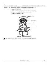
Страница 58: ...ing and Unpacking the Equipment When a new system arrives check that any components are not damaged and are not in short supply If shipping damage or shortage occurs contact the address shown in Chapter 1 1 Cut the four PLASTIC BANDs 2 Cut the adhesive tape and open top covers of paper carton Figure 3 1 Open top covers of paper carton Adhesive tape Plastic Bands 1 2 ...

Страница 59: ...t cont d 3 Take out the Paper pad 4 Take out console together with 2 interleavers from console package 5 Take out the interleavers beside Accessories Package 6 Take out Accessories Package Figure 3 2 Unpacking the equipment CAUTION Do not lift the unit by the rubber band Equipment damage may result Paper Pad Console and interleavers Console Package Accessories Package ...

Страница 60: ... Vivid e Basic Service Manual 3 6 Section 3 2 Receiving and Unpacking the Equipment Section 3 2 Receiving and Unpacking the Equipment cont d 7 Remove 2 interleavers 8 Remove plastic bag Figure 3 3 Removing interleavers and plastic bag Console Interleaver Interleaver ...

Страница 61: ...OGIQ e Vet LOGIQ i Vivid e Before moving store all loose parts in original accessory box or in back pack Return probes to original box Section 3 3 Packing the Equipment Please pack LOGIQ e LOGIQ e Vet LOGIQ i Vivid e in the reverse order of unpacking Figure 3 4 Labels on Package CAUTION Please carefully unpack the system and do not dispose the package of LOGIQ e LOGIQ e Vet LOGIQ i Vivid e so that...

Страница 62: ...ings for the LOGIQ e LOGIQ e Vet LOGIQ i Vivid e Scanner is found on a label located on the AC adapter 220 240VAC China 100 120VAC USA Japan 220 240VAC Europe Latin America 3 4 3 EMI Protection This Unit has been designed to minimize the effects of Electro Magnetic Interference EMI Many of the covers shields and screws are provided primarily to protect the system from image artifacts caused by thi...

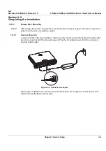
Страница 63: ...ystem may not be able to boot if power is recycled too quickly 3 5 1 1 Scanner Power On Lower the handle Plug the AC adapter output connector into the system DC input port located on the system s rear panel with the arrow side upward Plug the AC adapter power cord into a grounded protective earth outlet When power is applied to the scanner power is distributed to the Cooling Unit Control Panel LCD...

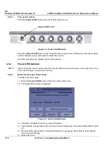
Страница 64: ... turning off a system wait at least ten seconds before turning it on again The system may not be able to boot if power is recycled too quickly 3 5 2 1 Back end Processor Power Down To power down the system 1 Press the Power On Off switch at the front of the system once 2 The System Exit window is displayed 3 Using the Trackball or Select key select Shutdown 4 The shutdown process takes a few secon...

Страница 65: ...ample Relocating the scanner 3 5 3 Transducer Connection 1 Carefully open the system LCD display plug the probe connector into the probe port then lock the probe latch upward NOTE Please ensure that the probe latch is in an unlocked position before you connect the probe to the system NOTE It is not necessary to turn OFF power to connect or disconnect a probe Figure 3 8 Connect the probe Probe Latc...

Страница 66: ...ns of the LOGIQ e LOGIQ e Vet LOGIQ i Vivid e console with old LCD are summarized in Figure 3 9 on page 3 12 Table 3 4 Physical Dimensions of LOGIQ e LOGIQ e Vet LOGIQ i Vivid e with old LCD Height Width Depth Unit Console Only Console with handle Console Only Console with handle Console Only Console with handle Unit 61 100 340 375 287 337 mm 2 4 3 9 13 4 14 8 11 3 13 3 inches Figure 3 9 Overall D...

Страница 67: ... Vivid e console with new LCD are summarized in Figure 3 10 on page 3 13 Table 3 5 Physical Dimensions of LOGIQ e LOGIQ e Vet LOGIQ i Vivid e with new LCD Height Width Depth Unit Console Only Console with handle Console Only Console with handle Console Only Console with handle Unit 70 100 346 372 295 340 mm 2 8 3 9 13 6 14 6 11 6 13 4 inches Figure 3 10 Overall Dimensions and weight with new LCD W...

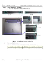
Страница 68: ... and new LCD Identify LCD type from the appearance of Ultrasound System 3 6 2 Electrical Specifications Figure 3 11 Difference between Old LCD and New LCD Table 3 6 Electrical Specifications for LOGIQ e LOGIQ e Vet LOGIQ i Vivid e Adapter Voltage Tolerances Current Frequency TWADP100 100 240 VAC 10 1 3A max 50 60Hz new LCD old LCD new LCD old LCD new LCD old LCD ...

Страница 69: ...U 120 USB LITEON LITEON Model eHAU 324 USB PLEXTOR PX L890UE USB LITEON LITEON eSAU108 DVDRW USB LITEON LITEON eUAU108 DVDRW USB LITEON LITEON eBAU108 DVDRW USB Wireless Lan Adapter NetGear WNA3100 USB NetGear WN111V2 USB NetGear WG111V3 USB Linksys Linksys WUSB54G USB 3 pedal footswitch Steute MKF 2 MED GP26 USB 1 pedal footswitch Whanam FSU2001 USB Whanam FSU 1000 USB USB Memory SanDisk CRUZER 2...

Страница 70: ... 800U USB Not supported by LOGIQ e R4 x x Vivid e R4 x x LOGIQ i R4 x x Video Transfer Pinnacle Pinnacle Video Transfer 8230 10022 11 USB Not supported by LOGIQ e R4 x x 5 0 x LOGIQ e Vet R5 0 x Vivid e R4 x x 5 0 x LOGIQ i R4 x x 5 0 x BarCode Reader Handheld Handheld 3800G USB Only supported by LOGIQ e R5 2 x LOGIQ e R6 x x LOGIQ e R7 x x LOGIQ e Vet R6 x x LOGIQ e Vet R7 x x Handheld Handheld 4...

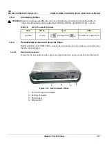
Страница 71: ... Connector Located on the rear panel are video input and output connectors power connector and ethernet port 1 Port for DC input AC Adapter 2 Docking Connector 3 SVGA Output 4 Ethernet port WARNING WARNING Equipment damage possibility Be sure to use the following recommended connecting cables to connect recording devices and a network with LOGIQ e LOGIQ e Vet LOGIQ i Vivid e console Table 3 8 List...

Страница 72: ...ed on the left side panel are two USB Ports for control connections for printer service tools and earphone port 1 Two interchangeable USB Port Digital Printers DVD RW and or FootSwitch etc 2 Earphone Port NOTE Each outer case ground line of peripheral accessory connectors are protectively grounded Signal ground lines are not isolated Figure 3 13 Left Side Panel 2 1 ...

Страница 73: ...f USB Table 3 10 Pin assignment of USB1 Table 3 11 Pin assignment of USB2 3 Pin assignment of RS232C for external VGA Connector D SUB 15Pin Female Table 3 12 Pin Assignments of RS232C for External VGA Pin No Signal Pin No Signal 1 20V 3 GND 2 20V 4 GND Pin No Signal Pin No Signal 1 5VDC 3 DATA 2 DATA 4 GND Pin No Signal Pin No Signal 1 5VDC 3 DATA 2 DATA 4 GND Pin No Signal Pin No Signal 1 RED 9 N...

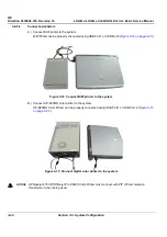
Страница 74: ... using USB Port1 or USB Port 2 Figure 3 14 on page 3 20 B Connect UP D23MD color printer to the system UP D23MD Color Printer can be properly connected using USB Port1 or USB Port 2 Figure 3 15 on page 3 20 Figure 3 14 Connect B W printer to the system Figure 3 15 Connect digital color printer to the system NOTICE HP Deskjet 470 HP Officejet Pro K5400 Color Printer must connect with PIT Printer Is...

Страница 75: ...ave worked successfully before Overall system configuration and other factors may also affect the success of creating a DVD CD The following media types have been tested LITEON highly recommends that you use the media types on this list when creating your DVDs CDs Not all brands of media have been tested and therefore you may encounter success with other brands not listed This list will be updated...

Страница 76: ...itch can be properly connected using USB Port1 or USB Port2 E Connect Wireless LAN Adapter to the system Wireless LAN Adapter can be properly connected using USB port F Connect the CRT to the system CRT can be properly connected using the SVGA output Figure 3 17 Connect Foot Switch to the system Figure 3 18 Connect Wireless LAN Adapter to the system 3 pedal footswitch 1 pedal footswitch Wireless L...

Страница 77: ...hapter 3 System Setup 3 23 3 6 5 4 Connect peripherals cont d G Connect the USB Memory to the system The USB Memory can be properly connected using USB port 1 or 2 H Connect the ECG to the system ECG can be properly connected using USB port 1 or 2 Figure 3 19 USB Memory Connection Figure 3 20 ECG ...

Страница 78: ...ration 3 6 5 4 Connect peripherals cont d I Connect the USB HDD to the system The USB Harddisk can be properly connected using USB port 1 and 2 J Connect the BarCode Reader to the system the BarCode Reader can be properly connected via USB port 1 or 2 Figure 3 21 Emergency Disk Connection Figure 3 22 BarCode Reader Connection ...

Страница 79: ...ndisk U3 USB Flash Drive is Predefined NOTE The Sandisk U3 USB Flash Drive is only available on LOGIQ e R6 x x R7 x x and LOGIQ e Vet R6 x x R7 x x Connect the security enabled Sandisk U3 USB Flash Drive into the system input the password in the pop up dialog Click OK to login click Cancel to cancel The Sandisk U3 USB Flash Drive can be used if the right password is entered An error message will d...

Страница 80: ...ash Drive will be locked if reaching the maximum number of failed password attempts NOTE Please refer to the operation manual of each peripheral for information needed by the user to operate the system safely For detailed installation information please refer to the LOGIQ e LOGIQ e Vet LOGIQ i Vivid e Peripheral Installation Instruction manual Figure 3 25 Wrong password error Figure 3 26 Sandisk U...

Страница 81: ...lay box and select OK NOTE Please refer to the operation manual of each peripheral for information needed by the user to operate the system safely NOTE For LOGIQ e R5 2 x R6 x x R7 x x LOGIQ e Vet R6 x x R7 x x the default set is dual it will not pop up Figure 3 28 For detailed installation information please refer to the LOGIQ e LOGIQ e Vet LOGIQ i Vivid e Peripheral Installation manual Figure 3 ...

Страница 82: ...x x the system supports 4C RS E8C RS 8C RS i12L RS 8L RS 3S RS 6S RS 12L RS i t739 RS P2D 9L RS Probes For Vivid e R4 x x the system supports 4C RS i12L RS 8L RS 3S RS Probes For Vivid e R5 0 x the system supports 4C RS i12L RS 8L RS 3S RS 8C RS 9L RS P2D Probes For Vivid e R5 2 x the system supports 4C RS 8C RS E8C RS 8L RS 9L RS 12L RS i12L RS 3S RS 6S RS P2D Probes For Vivid e R6 x x the system...

Страница 83: ...ATIVE SMALL PARTS VASCULAR PEDIATRICS LINEAR H40402LW 2377942 8L RS VALOX SMALL PARTS PERIPHERAL VASCULAR LINEAR H40402LT 2376127 3S RS VALOX CARDIOLOGY TRANSVAGINAL ABDOMEN SECTOR H4000PD 2355686 12L RS NORYL SMALL PARTS PERIPHERAL VASCULAR LINEAR H40402LY 5154514 9L RS VALOX SMALL PATS VASCULAR LINEAR H40442LL 5213143 i739 RS VALOX INTRAOPERATIVE LINEAR H40402LJ 2404995 t739 RS VALOX INTRAOPERAT...

Страница 84: ...er 16 Customizing Your System Table 3 15 List of Probes for LOGIQ e Vet Probe Name Material of Headshell Area of Using TYPE Catalog Number Part Number 4C RS Vet NORYL GENERAL PURPOSE CONVEX H40442LY 5198378 E8C RS Vet VALOX TRANSVAGINAL TRANSRECTAL MICRO CONVEX H41562LL 5134643 8C RS Vet VALOX VETERINARY PEDIATRIC NEONATAL MICRO CONVEX H41562LK 5134642 i12L RS Vet ABS GE INTRAOPERATIVE SMALL PARTS...

Страница 85: ...ite System Information Services Destination Devices TCP IP Settings Device Type Manufacturer Name IP Address Port AE Title 1 2 3 4 5 6 7 8 9 10 11 12 Name AE Title Dept LOGIQ SN Type Floor Room REV Comments CONTACT INFORMATION Name Title Phone E Mail Address Site IP Settings IP Address Subnet Mask Default Gateway Remote Archive Setup Remote Archive IP Remote Archive Name ...

Страница 86: ...00 Revision 16 LOGIQ e LOGIQ e Vet LOGIQ i Vivid e Basic Service Manual 3 32 Section 3 9 Loading Base Image Software Section 3 9 Loading Base Image Software Please refer to Section 8 3 Loading the System Software on page 8 4 ...

Страница 87: ...are Version check out 3 10 1 Functional Check out 1 Power on LOGIQ e LOGIQ e Vet LOGIQ i Vivid e scanner and wait until system booting to main screen 2 Press Utility Config key on control panel 3 Choose the About button on the right 4 Check whether Software version is the right version for use Figure 3 29 About Figure 3 30 Software version ...

Страница 88: ...elevant safety and user information is available during the operation and service of the complete system 3 11 1 Product Locator Installation NOTE The Product Locator Installation Card shown may not be same as the provided Product Locator card 3 11 2 User Manual s User Check that the correct User Manual s for the system and software revision is included with the installation Specific language versi...

Страница 89: ...GIQ e Vet LOGIQ i Vivid e console diagnostics by using the built in service software and power supply adjustments Section 4 2 Required Equipment To perform these tests you ll need any of the sector linear or convex transducers normally you should check all the transducers used on the system Table 4 1 Contents in chapter 4 Section Description Page Number 4 1 Overview 4 1 4 2 Required Equipment 4 1 ...

Страница 90: ...output connector into the system DC input port located on the system s rear panel with the arrow side upward Plug the AC adapter power cord into a grounded protective earth outlet CAUTION SYSTEM REQUIRES ALL COVERS Operate this unit only when all board covers and frame panels are securely in place The covers are required for safe operation good system performance and cooling purposes NOTICE Lockou...

Страница 91: ...s pressed once the Back end Processor starts and the software code is distributed to initiate the scanner No status messages are displayed during this process 4 3 2 Power Off Shutdown NOTE After turning off a system wait at least ten seconds before turning it on again The system may not be able to boot if power is recycled too quickly 4 3 2 1 Back end Processor Power Down To power down the system ...

Страница 92: ...ntenance Reboot Full Maintenance Reboot will fully restart the whole system for performance improvement NOTE It s recommended to do Full Maintenance Reboot at least daily or when system starts to slow down or lag in its reaction 1 Press the Power On Off switch at the front of the system once 2 Click Full Maintenance Reboot 3 Full Maintenance Reboot dialog is displayed 4 3 2 4 Exit only activated f...

Страница 93: ...ystem 4 3 3 1 Archiving Presets to an DVD R Disk or USB memory device 1 Insert an empty blank DVD R disk into the DVD RW 2 Access to the Utility Config Menu and select System The Backup sheet will be shown on the LCD display 3 Select the item to Backup Restore 4 Enter backup destination or browse through the disk to locate the destination 5 Select Backup now The backup status for each item is disp...

Страница 94: ...t Tagout requirements by ensuring you are in total control of the AC power plug at all times during the service process To apply Lockout Tagout 1 Plan and prepare for shutdown 2 Shutdown the equipment 3 Isolate the equipment 4 Apply Lockout Tagout Devices 5 Remove battery 6 Control all stored and residual energy 7 Verify isolation All potentially hazardous stored or residual energy is relieved NOT...

Страница 95: ...l Chapter 4 Functional Checks 4 7 4 3 6 System Features 4 3 6 1 Control Panel 1 TGC 2 New Patient 3 End Exam 4 Mode Gain Auto Keys 5 Preset Key 6 Imaging Measurement Keys 7 Depth Zoom Ellipse 8 Image Keys 9 Print Keys 10 Freeze 11 Keyboard Figure 4 4 Control Panel Tour 1 2 3 4 5 6 7 8 9 10 11 ...

Страница 96: ... i Vivid e SoftMenu Key Tour In general there are two types of softMenu keys Paddle Switch and adjustable knobs 1 The Paddle Switch is used to access and adjust the Sub SoftMenu 2 Press the adjustable knobs to toggle option menu between line one and line two 3 Rotate the adjustable knobs to adjust the corresponding parameters Figure 4 5 SoftMenu Key Tour 2 1 3 ...

Страница 97: ...e 3 Acoustic Output Readout 15 TGC not shown on the image 4 GE Symbol Probe Orientation Marker Coincides with a probe orientation marking on the probe 16 Body Pattern 5 Image Preview 17 Depth Scale 6 Gray Color Bar 18 SoftMenu 7 Cine Gauge 19 Caps Lock On Off 8 Measurement Summary Window 20 Start menu icon 9 Image 21 Battery icon 10 Measurement 22 Network icon 11 Results Window 23 Trackball Functi...

Страница 98: ...n 3 6 6 Available Probes on page 3 28 in Chapter 3 Installation to the System probe connector 2 Turn ON the scanner if it isn t turned on already NOTE The keyboard layout varies from each Product the following figures show LOGIQ e R5 x x as an example Figure 4 7 Controls available in B Mode Figure 4 8 B Mode Screen Picture Example SoftMenu Key Primary Menu Scan Area B Mode Zoom Depth Freeze Second...

Страница 99: ...p the beam for specific area Press the control to toggle between Focus Position and Focus Number Press Up Down Button to move or adjust the focal numbers 5 Activate Auto Optimize Optimize the image based upon a specified region of interest or anatomy Press the Center Button in the Gain Dial to toggle the ATO ACE On and Off 7 Adjust Time Gain Compensation TGC Amplifies the returning signals to corr...

Страница 100: ...or shift up to a higher frequency 6 Adjust Frame Average Temporal filter that averages frames together This has the effect of presenting a smoother softer image For LOGIQ e LOGIQ e Vet and LOGIQ i Adjust DDP Temporal filter that averages frames together This has the effect of presenting a smoother softer image For Vivid e 7 Adjust Rotation Rotates the image by selecting the value from the pop up m...

Страница 101: ...ontrols 4 3 8 1 Preparations 1 Connect one of the probes listed in 3 6 6 Available Probes on page 3 28 in Chapter 3 Installation to the System probe connector 2 Turn ON the scanner if it isn t turned on already Figure 4 9 Controls available in M Mode Figure 4 10 M Mode Screen Picture Example Primary Menu Secondary Menu M Mode Gain M D Cursor ...

Страница 102: ...Panel Controls Step Task Expected Result s Comments 1 Press M Mode key M Mode Starts 2 Adjust Gain Controls the amount of echo information displayed in an image Turn B Mode dial to the left right to increase decrease Gain Gain displays on the monitor in Gn dB 3 Display M Mode Cursor Displays the M Mode cursor on the B Mode image Press Cursor and Trackball to position M Mode Cursor ...

Страница 103: ...aries by enhancing the gray scale differences corresponding to the edges of structures Adjustments to M Mode s edge enhancement affects the M Mode only For Vivid e 4 Activate Gray Map Determines how the echo intensity levels received are presented as shades of gray 6 Activate Colorize Enables gray scale image colorization To deactivate reselect a Gray Map 7 Activate Full Timeline Displays only tim...

Страница 104: ...ode Checks 4 3 9 1 Preparations 1 Connect one of the probes listed in 3 6 6 Available Probes on page 3 28 in Chapter 3 Installation to the System probe connector 2 Turn ON the scanner if it isn t turned on already Figure 4 11 Controls available in Color Flow Mode Figure 4 12 CFM Mode Screen Picture Example Primary Menu CF Mode Gain Secondary Menu ...

Страница 105: ...4 3 9 2 Color Flow Mode OP Panel Controls Table 4 7 Color Flow Mode OP Panel Controls Step Task Expected Result s comments 1 Press CFM Mode key CFM Mode Starts 2 Adjust Gain Amplifies the overall strength of the echoes processed in the Color Flow window Turn the Gain dial CFM Mode key to the left right to increase decrease Gain ...

Страница 106: ...nt perspective Press Invert to reverse the color map 7 Adjust LIne Density Trades frame rate for sensitivity and spatial resolution If the frame rate is too slow reduce the size of the region of interest select a different line density setting or reduce the packet size For LOGIQ e LOGIQ e Vet and LOGIQ i Adjust Frame Rate Trades frame rate for sensitivity and spatial resolution If the frame rate i...

Страница 107: ...s to select specific transparency map 15 Focus Position Increases the number of transmit focal zones or moves the focal zone s so that you can tighten up the beam for a specific area A graphic caret corresponding to the focal zone position s appears on the right edge of the image 16 Power output Optimizes image quality and allows user to reduce beam intensity 10 increments between 0 100 Values gre...

Страница 108: ... 10 1 Preparations 1 Connect one of the probes listed in 3 6 6 Available Probes on page 3 28 in Chapter 3 Installation to the System probe connector 2 Turn ON the scanner if it isn t turned on already Figure 4 13 Controls available in Doppler Mode Figure 4 14 Doppler Mode Screen Picture Example Primary Menu Secondary Menu M D Cursor PW Mode Gain B Pause Enter ...

Страница 109: ...ain Amplifies the overall strength of the echoes processed in the Color Flow window Turn the Gain dial PW Mode key to the left right to increase decrease Gain 3 Display M D Mode Cursor Displays the M D Mode cursor on the B Mode image Press Cursor and Trackball to position sample volume graphic Click SV gate to adjust sample volume gate size 4 B Pause Toggle between simultaneous and update presenta...

Страница 110: ... trace direction 7 Invert Vertically inverts the spectral trace without affecting the baseline position Press invert to invert the spectral trace The Plus and Minus signs on the velocity scale reverse when the spectrum is inverted 8 Auto Calculation Enables or disables auto calculation For LOGIQ e LOGIQ e Vet and LOGIQ i 9 Modify Calcs Activates the window to modify the auto calculation items 10 T...

Страница 111: ...ingle gate PRF capability the system automatically switches to high PRF mode Multiple gates appear and HPRF is indicated on the display For Vivid e 18 Trace Sensitivity Adjusts the sensitivity to get more accurate envelope trace 19 Time Resolution Adjusts the resolution in frequency domain 20 Spectral Average Optimizes the smoothness of the spectrum Different levels can be selected 21 Power output...

Страница 112: ...GIQ i press F6 on the keyboard to enter CW mode F6 is the predefined function key for CW which can be configured in Utility Config Admin Function Key preset menu For LOGIQ e R7 x x and LOGIQ e Vet R7 x x press F9 on the keyboard to enter CW mode For Vivid e press CW Key on the keyboard The Doppler Spectrum appears along with the CW Top Sub Menu Menu Figure 4 1 CWD Screen The following CW parameter...

Страница 113: ...point press SET The system fixes the first caliper and displays a second active caliper 4 To position the second caliper move the TRACKBALL 5 Adjust the ELLIPSE an ellipse with an initial circle shape appears 6 To position the ellipse and to size the measured axes move the calipers move the TRACKBALL 7 To increase the size rotate the ELLIPSE button clockwise To decrease the size contrarotate the E...

Страница 114: ...be in its storage box 4 3 14 Using Cine 4 3 14 1 Activating CINE Press Freeze then roll the Trackball to activate CINE To start CINE Loop playback press Run Stop To stop CINE Loop playback press Run Stop 4 3 14 2 Quickly Move to Start End Frame Press First to move to the first CINE frame press Last to move to the last CINE frame 4 3 14 3 Start Frame End Frame Press the Start Frame Two Button Softk...

Страница 115: ...o move through CINE memory one frame at a time 4 3 15 Image Management QG For Image Management functionality refer to the LOGIQ e LOGIQ e Vet LOGIQ i Vivid e Quick Guide It talks about several topics Clipboard Printing Images Browsing and Managing an Exam s Stored Image Connectivity and Dataflow Concept and Creation Starting an Exam Configuring Connectivity TCP IP Services Destinations Buttons Vie...

Страница 116: ...the backup media 3 Select the media type from the drop down menu 4 Enter the label for the media as shown in Figure 4 15 It is best to use all capital letters with no spaces or punctuation marks Press Format 5 The Ultrasound system displays a pop up menu as shown in Figure 4 16 When the formatting has been completed press OK to continue 6 If desired verify that the format was successful by returni...

Страница 117: ...he drive 2 On the Keyboard press UTILITY CONFIG 3 On the LCD display press SYSTEM 4 On the LCD display select BACKUP RESTORE NOTE If you are not logged in as GE Service or with administrator privileges the Operator Login window is displayed Log on with administrator privileges 5 In the Backup list select Patient Archive Report Archive and User Defined Configuration 6 In the Media field select DVD ...

Страница 118: ... window is displayed Log on with administrator privileges 5 In the Restore list select Patient Archive Report Archive and User Defined Configuration 6 In the Media field select the Backup Restore DVD RW or USB memory device 7 Select RESTORE The system performs the restore As it proceeds status information is displayed on the Backup Restore screen After the Restore completes the system will automat...

Страница 119: ...label media by date NOTE Images will be moved from the hard disk drive by date Therefore the best way to label media is by date When images are moved to the archive media they will be deleted from the system hard disk drive However the patient database backed up earlier maintains pointers to the location of the images on the archive media 5 Select Backup Restore then EZBackup Move NOTE For LOGIQ e...

Страница 120: ...6 4 Archiving Images cont d 7 Press PATIENT and set the Dataflow to store images directly to DVD ROM 8 From the image screen press EZBACKUP MOVE The Move Images pop up appears 9 Press Next on pop up message 10 A media check message appears Press OK to continue Figure 4 21 Image Archive Move Pop up Menu Figure 4 22 Media check message ...

Страница 121: ... Press Finish after Backup Move complete All databases presets and images should now be saved to removable media 4 3 16 5 Emergency Repair Disk 1 Connect the USB HDD to system 2 Select Backup Restore then Emergency Repair Disk 3 Select Reminder Dialog Interval Days Figure 4 23 EZBackup Move complete Figure 4 24 Emergency Repair Disk Reminder Dialog Interval Days ...

Страница 122: ...eral Procedure 4 3 16 5 Emergency Repair Disk cont d 4 Return to scan mode Press Ctrl B the Emergency Disk Making window pop up appears 5 Press Next on pop up message 6 A storage information message appears Press Next to continue Figure 4 25 Emergency Disk Making Pop up Menu Figure 4 26 Storage Information message ...

Страница 123: ... 35 4 3 16 5 Emergency Repair Disk cont d 7 Press Finish after Emergency Disk Making complete All databases presets and images should now be saved to Emergency Disk 8 Press Ctrl R Emergency Disk Recovery will pop up 9 Press Next on pop up message Figure 4 27 Emergency Disk Making Complete Figure 4 28 Emergency Disk Recovery ...

Страница 124: ...e Manual 4 36 Section 4 3 General Procedure 4 3 16 5 Emergency Repair Disk cont d 10 A recovery information message appears Press Next to continue 11 Press Finish after Emergency Disk Recovery complete Figure 4 29 Recovery Information message Figure 4 30 Emergency Disk Recovery Complete ...

Страница 125: ...nment of Printer Keys For LOGIQ e LOGIQ e Vet LOGIQ i the default function for Print1 3 Keys is P1 store image P2 print P3 USB Quick Save Print1 3 Keys can also be assigned as desired by the customer For Vivid e the default function for Store Key and Print1 2 Keys is Store store image P1 print P2 USB Quick Save Store Key and Print1 2 Keys can also be assigned as desired by the customer 5 Check tha...

Страница 126: ...GE Direction 5370626 100 Revision 18 LOGIQ e LOGIQ e Vet LOGIQ i Vivid e Basic Service Manual 4 38 Section 4 5 Peripheral Checks This page was intentionally left blank ...

Страница 127: ... 5 1 Overview This chapter explains LOGIQ e LOGIQ e Vet LOGIQ i Vivid e s system concepts component arrangement and subsystem function It also describes the Power Distribution System PDS and probes Table 5 1 Contents in Chapter 5 Section Description Page Number 5 1 Overview 5 1 5 2 Block Diagrams and Theory 5 2 5 3 Power Diagrams 5 6 5 3 Power Diagrams 5 6 5 4 Common Service Platform 5 10 ...

Страница 128: ...it DC DC HV Ctrl SMBUS I F DC DC high voltage control smart bus interface TUSC FPGA LOGIQ e LOGIQ e Vet LOGIQ i Vivid e Ultrasound controlling and Image data transfer FPGA Figure 5 1 LOGIQ e LOGIQ e Vet LOGIQ i Vivid e System Block Diagram Probe Connector TX64 RX64 TMST RFI Carrier HV unit Battery Charger and MUX AC Adapter Li Ion Battery Keyboard A N key Trackball U S key TGC Soft menu key LCD 15...

Страница 129: ...aging 2D Color Flow M Mode Black and White imaging Doppler A number of combinations of the above LOGIQ e LOGIQ e Vet LOGIQ i Vivid e is a digital beam forming system that can handle up to 128 elements linear probes Signal flow from the Probe Connector Panel to the Front End to the Mid Processors and Back End Processor and finally to the LCD and peripherals System configuration is stored on a hard ...

Страница 130: ...3 External I O External I O The external I O is the interface between the scanner and all external items Examples wireless network USB interface medical grade printer and external medical grade SVGA displayer 5 2 4 Peripherals DVD RW and a Black White Video Printer can be connected to the external I O Figure 5 2 External I O module overview ...

Страница 131: ... e Vet LOGIQ i Vivid e Basic Service Manual Chapter 5 Components and Functions Theory 5 5 5 2 5 Wiring TX64 Transmit board RX64 Front end processing board TMST Master board PWR SW Power Switch FPC Flexible Print Circuit board Figure 5 3 Wiring Diagram ...

Страница 132: ...d no main power switch located on this power pack 5 3 2 AC Power The mains cord has plugs in one side end A male plug connects to the mains outlet on site The mains voltage is routed to the AC power pack through a Circuit Breaker located on the site The Circuit Breaker is of the auto fuse type if for some reason the current grows to high the switch will automatically break the power From the Main ...

Страница 133: ...n the battery and the output of AC Pack If the output of AC Pack is available the power input of Charge Board Unit should be from the AC Pack and the battery will be charged if it s not full This block will be also in charge of the battery charging monitor to avoid the battery over heat and over charging charging will be shut off automatically if battery is charged fully The battery will discharge...

Страница 134: ... Power Diagrams 5 3 4 Air Flow Distribution The two air flow passes allow the scanner to be cooled down as shown in the figure above Path A Bottom front CPU Assy Bottom left for TMST CPU Assy cooling Path B Bottom front TX64 RX64 Bottom right for TX64 RX64 cooling Figure 5 5 Air Flow Inside the Scanner A A B B ...

Страница 135: ...vice Manual Chapter 5 Components and Functions Theory 5 9 5 3 5 Fans The scanner contains the four fans at the following positions for producing an air flow One fan assy On the Left side for air flow path A One fan assy On the Right side for air flow path B Figure 5 6 Left Right Fans ...

Страница 136: ...training and service costs 5 4 2 Global Service User Interface GSUI 5 4 2 1 Internationalization The user interface provided by the service platform is designed for GE personnel and as such is in English only There is no multi lingual capability built into the Service Interface 5 4 2 2 Service Login Select Utility Config Service This button links the user to the service login screen 5 4 2 3 Access...

Страница 137: ...ble around the immovable object refer to Figure 5 9 on page 5 11 2 Make sure and rotate the key to the right unlocked position 3 Insert the lock into the Kensington security slot in the system side cover refer to Figure 5 9 on page 5 11 4 Rotate the key to the left locked position 5 For more information visit www kensington com NOTE Full maintenance reboot should be selected after the service dong...

Страница 138: ...Q e Vet LOGIQ i Vivid e Basic Service Manual 5 12 Section 5 4 Common Service Platform 5 4 3 Service Home Page The navigation bar at the top of the screen allows the user to select from several tools and utilities Figure 5 10 Customer Service Home Page ...

Страница 139: ...wn sub menus and an Exit selection The Service Interface allows scanner logs to be viewed by all service users The log entries are color coded to identify the error level severity at a glance The Service Interface supports the transfer of these logs to local destinations such as the CD ROM drive Table 5 3 Log Entry Key Severity Error Level Color Code 1 Information Green 2 Warning Blue 3 Error Red ...

Страница 140: ...alculationMade CalculationTime HelpUsage ProductName SystemSWRev NoOfSWModules SystemPowerOnTime SystemIdleTime NoOfBoards ProbeChangedDate ProbeChangedTime ProbeChangedStatus NoOfProbeSlots NoOfProbes ProbeID ProbeSerialNumber and ActiveExamProbes Temperature Log entry headings include Time Stamp Error Level Package CPU Internal Temp TMST Process Temp TMST Internal Temp TMST Remote Temp TX64 Proc...

Страница 141: ...l Log contents with the package on the x axis and incident count on the y axis Plot Page Allows for the color coded plot of all Page contents with the package on the x axis and incident count on the y axis 5 4 4 3 Search On the Text Search sub menu of the Search category users enter case sensitive text they wish to find This filter field works well for filtering the Sys log file for the word fail ...

Страница 142: ...vision 18 LOGIQ e LOGIQ e Vet LOGIQ i Vivid e Basic Service Manual 5 16 Section 5 4 Common Service Platform 5 4 4 4 Exit The sub menu Exit Log Viewer returns the user to the Service Desktop home page Figure 5 14 Exit Log Sub Menu ...

Страница 143: ...ts are executable by both local and remote users The Service Platform provides top level diagnostic selection based on the user s level and login access permissions Remote access will require disruptive diagnostic permissions to run Acquisition diagnostics 5 4 5 2 Diagnostic Reports Diagnostic tests return a report to the Service Platform The platform retains the report and allows for future viewi...

Страница 144: ...form 5 4 6 Image Quality The Image Quality page is intended to contain tools for troubleshooting image quality issues 5 4 7 Calibration The Calibration page is intended to contain the tools used to calibrate the system Figure 5 16 Image Quality Page Figure 5 17 Calibration Page FIELD IS NOT YET POPULATED FIELD IS NOT YET POPULATED ...

Страница 145: ...tion page is intended to be used to setup various configuration files on the system The Service Platform is the access and authorization control for remote access to the configuration subsystem The enable disable of software options can be done from this Configuration page 5 4 9 Utilities The Utilities page contains several miscellaneous tools Figure 5 18 Configuration Page ...

Страница 146: ...0 Replacement The Replacement page is intended to contain the tools used to track replacement parts used in the system 5 4 11 PM The PM page is intended to contain the tools used in periodic maintenance of the system Figure 5 19 Part Replacement Page Figure 5 20 Planned Maintenance Page FIELD IS NOT YET POPULATED FIELD IS NOT YET POPULATED ...

Страница 147: ... 6 1 Chapter 6 Service Adjustments Section 6 1 Overview 6 1 1 Purpose of this chapter 6 This section describes how to test and adjust the scanner These tests are optional You may use them to check the system for errors Table 6 1 Contents in chapter Section Description Page Number 6 1 Overview 6 1 6 2 Monitor Adjustments 6 2 ...

Страница 148: ...l 6 2 Section 6 2 Monitor Adjustments Section 6 2 Monitor Adjustments 6 2 1 Adjustments Procedures To adjust the brightness and volume 1 Press Ctrl brightness key together up down located on the keyboard 1 Press Ctrl volume key together left right located on the keyboard Figure 6 1 LCD Monitor ...

Страница 149: ... maintain image quality and system operation Very basic host system and board level diagnostics are run whenever power is applied Some Service Tools may be run at the application level However most software tests are required Table 7 1 Contents in Chapter 7 Section Description Page Number 7 1 Overview 7 1 7 2 Gathering Trouble Data 7 2 7 3 USB Quick Save 7 4 7 4 Screen Captures 7 6 7 5 Global Serv...

Страница 150: ...ck to the manufacturer for analysis There are different options to acquire this data that would give different results 7 2 2 Collect Vital System Information The following information is necessary in order to properly analyze data or images being reported as a malfunction or being returned to the manufacturer Product Name LOGIQ e LOGIQ e Vet LOGIQ i Vivid e From the Utility System About screen App...

Страница 151: ...s Crash Log Power Supply Temperature NOTE Power Supply and Temperature logs are not currently being updated by the LOGIQ e LOGIQ e Vet LOGIQ i Vivid e This Alt D function is available at all times When Alt D is pressed a menu box appears that allows for A place to enter a description of the problem A choice to store to a pre formatted DVD R RD Removable Disk or to the Export directory D export The...

Страница 152: ...ve However the default is for the Image Area only or the customer may have customized the default Key function Here take LOGIQ e for example and the P3 key is the factory default print key to accomplish the USB Quick Save 7 3 2 Check and Record the P3 Key Function Check the function of the default Key in the event that the customer may have made some customized settings 1 Click Utility Config on t...

Страница 153: ...ers related to the service 7 3 3 Setting the P3 Key to USB Quick Save If the P3 Key is not set to USB Quick Save 1 While on the Connectivity screen with the Buttons tab displayed go to the Destinations list 2 From the list select USB Quick Save Press to add the selection to the Printflow View section 3 Ensure that the Physical Print Buttons section for capture Area is set to Image Area and No Imag...

Страница 154: ...2 Select Connectivity from the Utilities Menu 3 Select the Buttons tab on the Connectivity screen 4 In the Physical Print Buttons field select Print1 The Connectivity Buttons Screen will be displayed like the one shown in Figure 7 2 on page 7 4 If P1 is not set to Whole Screen as shown in Figure 7 2 on page 7 4 proceed to step 5 to record the customer s customized settings 5 In the Destinations se...

Страница 155: ...pturing a Screen cont d 3 Click FREEZE to unfreeze the image to view the image screen and the snapshots displayed on the bottom 4 Highlight the snapshot to be stored 5 Select Menu on the right side of the image screen then highlight and select SAVE AS Figure 7 3 Select Image to Capture Figure 7 4 Menu Save As Clipboard Thumbnai ls Menu Save As ...

Страница 156: ...ey to Customer s Functionality If the customer had programmed the P3 Key to a function other than screen capture restore that functionality recorded in section 7 4 1 on page 6 Refer to Figure 7 2 1 Click Utility Config on the keyboard 2 Select Connectivity from the Utilities Menu 3 Select the Buttons tab on the Connectivity screen 4 In the Physical Print Button field select Print1 5 In the Destina...

Страница 157: ...n 7 5 Global Service User Interface GSUI 7 5 1 Enter global service user interface 1 Press Utility Config Service see Figure 7 6 on page 7 9 1 Select GE Service in option of User Level of GEMS Service Home page and input correct password press OK button See Figure 7 7 on page 7 9 Figure 7 6 system Service button Figure 7 7 Service Login Page ...

Страница 158: ...iagnostic control and Operator feedback 7 5 3 1 Button This button has two modes each with appropriate text Execute to start the diagnostic and Abort to stop a diagnostic The button can also be disabled 7 5 3 2 Loop Count This is an editable text field that will only accept numeric values with 4 digits or less When the button is configured as an execute button and pressed the loop count field will...

Страница 159: ...xt Message Displays either a starting message or aborting message as well as the diagnostic completion status 7 5 3 5 Background Color Initially gray the Control Frame background color changes upon completion of a diagnostic to indicate completion status Fail Red Pass Green Neither pass nor fail Set back to Gray for example final code status is Aborted ...

Страница 160: ...s two selections 7 6 1 1 Disruptive Mode Allows you to enable or disable disruptive mode troubleshooting 7 6 1 2 System Shutdown Allows for system shutdown from the diagnostic menu Select to Restart System or Shutdown System Also select to retain Disruptive Mode or Not After submitting to restart or shutdown a confirmation screen gives one last chance to confirm or cancel the request ...

Страница 161: ...iagnostics Troubleshooting 7 13 7 6 2 PC Diagnostics Non Interactive Tests 7 6 2 1 Essential Tests 7 6 2 2 System Board 7 6 2 3 Hard Disk Drive Surface Scan 7 6 2 4 Hard Disk Drive Quick Test 7 6 2 5 PCIBus 7 6 2 6 Video Card 7 6 2 7 Network Interface 7 6 2 8 CMOS 7 6 2 9 DRAM Memory 7 6 2 10 Parallel Port ...

Страница 162: ...tion 7 6 Common Diagnostics 7 6 3 PC Diagnostics Interactive Tests 7 6 3 1 Keyboard Test 7 6 3 2 Mouse Test 7 6 3 3 Audio Card Test only for LOGIQ e R5 2 x R6 x x R7 x x LOGIQ e Vet R6 x x R7 x x 7 6 4 Restart the system after diagnostics Always shutdown the system and reboot after a diagnostics session ...

Страница 163: ...roubleshooting 7 15 Section 7 7 Network and Insite II Configuration 7 7 1 Network Configuration 7 7 1 1 Wire LAN Network 1 Connect system with network 2 Press Utility Config Connectivity TCPIP in IP Settings window check the Enable DHCP box In Network Speed box choose the proper speed available Figure 7 9 Enable DHCP ...

Страница 164: ...o setup static IP address uncheck Enable DHCP option input static address in IP Address box Subnet Mask and Default Gateway box In Network Speed box choose the proper speed available 3 Click Save in popped up dialog choose Ok 4 After reboot the network icon at the left bottom of screen turns green Figure 7 10 Input static address Figure 7 11 Save and reboot inquiry dialog Figure 7 12 Network icon ...

Страница 165: ...Start at the left bottom of screen and select Network Connections 3 In the pop up window choose Wireless Network Connection Click it with cursor key then select View Available Wireless Networks Figure 7 13 Start menu Figure 7 14 Wireless Network Connection configuration For LOGIQ e R5 x x R6 x x R7 x x Vivid e R5 x x R6 x x LOGIQ i R5 x x LOGIQ e Vet R6 x x R7 x x For LOGIQ e R4 x x LOGIQ i R4 x x...

Страница 166: ...NOTE If an encrypted network has been selected input Network key in Wireless Network Connection dialog box displayed and click Connect 5 The network icon at the left bottom of screen turns green Figure 7 15 Wireless Network Connection dialog box Figure 7 16 Network key input Figure 7 17 Network icon NOTE To manually configure a wireless network the involvement of the IT department is mandatory For...

Страница 167: ...n page 9 7 To use Pilot Server on Configuration page choose Questra Agent Configuration in left column Select Advanced Configuration then choose Others as server type and manually input pilot address and click SAVE NOTE If system is within GE network choose Development as server type and do not need step 9 enter Proxy Server address Figure 7 18 Advanced_Configuration page out of GE network Figure ...

Страница 168: ...nsite II Configuration cont d 8 Change to Device Information page enter Device and Serial Number as the serial number of that system then press Modify Device Configurations NOTE The Device name and Serial Number entered should be unique on server It can be read from the rating plate label Figure 7 20 Device_Information page Figure 7 21 Rating plate label ...

Страница 169: ...Vivid e Basic Service Manual Chapter 7 Diagnostics Troubleshooting 7 21 7 7 2 Insite II Configuration cont d 9 Change to Proxy_Configuration page enter Proxy Server Address as 3 20 128 6 and Proxy Server Port as 88 then press SAVE Figure 7 22 Proxy_Configuration page ...

Страница 170: ...7 7 Network and Insite II Configuration 7 7 2 Insite II Configuration cont d 10 Change to Diagnostics page Enable Disruptive Mode at Service side by pressing Yes 11 Customer will receive a request of Service side click Yes to accept Figure 7 23 Enable Disruptive Mode Figure 7 24 Accept requirement of Service ...

Страница 171: ...ual Chapter 7 Diagnostics Troubleshooting 7 23 7 7 2 Insite II Configuration cont d 12 Service can do Remote Diagnostics successfully 13 Press power switch and choose Full Maintenance Reboot to reboot system Figure 7 25 Remote Diagnostic successful Figure 7 26 Full Maintenance Reboot window ...

Страница 172: ...x R7 x x 1 Enter global service user interface and log in as GE Service See 7 5 1 2 On Configuration page select Insite ExC Agent Configuration in the left column fill in the information in Agent Configuration choose PPODUCT as Enterprise server in Advanced Configuration please keep the default settings for other items then click Submit Changes NOTE The BOLD items can not be left blank Figure 7 27...

Страница 173: ...ruptive Mode in the left column Check whether the Disruptive Mode Status is Enabled if not click Yes to change the Disruptive Mode Status as Enabled See Figure 7 28 on page 7 25 There is another way to Set Disruptive Mode Status as Enabled Click Insite Icon in system status bar choose Connect clinical Lifeline the Insite Icon will change to RED do not need to change if the Insite icon is already R...

Страница 174: ...7 3 Insite II Configuration For LOGIQ e R6 x x R7 x x and LOGIQ e Vet R6 x x R7 x x cont d 4 Customer will receive a request of Service side click Yes to accept See Figure 7 30 on page 7 26 5 Service can do Remote Diagnostics successfully See Figure 7 31 on page 7 26 Figure 7 30 Accept requirement of Service Figure 7 31 Remote Diagnostic successful ...

Страница 175: ... 7 27 7 7 3 Insite II Configuration For LOGIQ e R6 x x R7 x x and LOGIQ e Vet R6 x x R7 x x cont d 6 Press power switch select Full Maintenance Reboot to reboot system see Figure 7 32 on page 7 27 7 In remote server side select the device type in DEVICE TYPE Figure 7 32 Full Maintenance Reboot window Figure 7 33 device type window ...

Страница 176: ... 3 Insite II Configuration For LOGIQ e R6 x x R7 x x and LOGIQ e Vet R6 x x R7 x x cont d 8 Select Update Software in the category of SERVICE 9 The page of software package shows up select the correct software package in the list Then select SCHEDULE to set a proper time to upgrade the software Figure 7 34 Update software Figure 7 35 software package ...

Страница 177: ...bleshooting 7 29 7 7 3 Insite II Configuration For LOGIQ e R6 x x R7 x x and LOGIQ e Vet R6 x x R7 x x cont d 10 Click icon on the schedule page to set up a schedule Fill in the name and time then click Add 11 Then the active schedule is shown on the SCHEDULE page Figure 7 36 New schedule page Figure 7 37 Active Schedule ...

Страница 178: ...icon will show in the status bar 13 Press Power button The SYSTEM EXIT window shows up Click Decline the system will not download the software and the Insite icon in the status bar will not shown Click Download the system will begin to download the software NOTE If the administrator is in remote side press Alt F1 to display the Frontpanel simulator Select the On Off button and the system exit wind...

Страница 179: ...x x R7 x x cont d NOTE Make sure the system administrator is logged on as ADM or the system will indicate such message 14 The system begins to download the software and wait until the process complete If you click Pause the download process will be paused Click Download to re start the process If you click Cancel the download process will stop Figure 7 41 System exit error Figure 7 42 Software dow...

Страница 180: ...II Configuration 7 7 3 Insite II Configuration For LOGIQ e R6 x x R7 x x and LOGIQ e Vet R6 x x R7 x x cont d 15 When the download is complete it will show the window below 16 Restart the system and the system CD will be loaded as shown in Figure 7 44 on page 7 32 Figure 7 43 Download Complete window Figure 7 44 System CD loading ...

Страница 181: ... Vet R6 x x R7 x x cont d 17 After the system is on login as ADM Press Power button and the system exit window displays Select Verify 18 It will show the verify items Select Passed and sign the signature the upgrade completes If any of the 10 items fails the system will remind the user to restart the system to rollback to the previous version Figure 7 45 System exit verify window Figure 7 46 Verif...

Страница 182: ...GE Direction 5370626 100 Revision 18 LOGIQ e LOGIQ e Vet LOGIQ i Vivid e Basic Service Manual 7 34 Section 7 7 Network and Insite II Configuration This page was intentionally left blank ...

Страница 183: ...escription Page Number 8 1 Overview page 8 1 8 2 Disassembly Re assembly of LOGIQ e LOGIQ e Vet LOGIQ i Vivid e page 8 1 8 2 1 Warning and Caution page 8 1 8 2 2 Handle Assy FRU No 313 page 8 2 8 3 Loading the System Software page 8 4 8 4 Checks after FRU replacement Debrief Guidelines page 8 23 WARNING WARNING ONLY QUALIFIED SERVICE PERSONNEL SHOULD REMOVE ANY COVERS OR PANELS ELECTRICAL HAZARDS ...

Страница 184: ...the Handle Assy FRU No 313 8 2 2 1 Tools Plier 8 2 2 2 Needed Manpower 1 person 2 minutes travel 8 2 2 3 Preparations Shut down the system then disconnect the AC DC power cord and remove the battery 8 2 2 4 Removal Procedure Refer to Figure 8 1 on page 8 3 1 Unscrew the two handle caps on both sides of the system the rotation direction is counterclockwise 2 Pull out the Handle 8 2 2 5 Mounting pro...

Страница 185: ... Direction 5370626 100 Revision 18 LOGIQ e LOGIQ e Vet LOGIQ i Vivid e Basic Service Manual Chapter 8 Replacement Procedures 8 3 8 2 2 Handle Assy FRU No 313 cont d Figure 8 1 Handle Assy Disassembly 1 2 ...

Страница 186: ... the system software with DVD Refer to section 8 3 1 Loading Base Image Software with DVD on page 8 5 from page 8 5 to page 8 9 Load the system software with USB memory stick Refer to Refer to section 8 3 2 Loading the System Software with USB Memory Stick on page 8 10 from page 8 10 to page 8 16 NOTE When upgrading the software with DVD or USB please remove the system from the docking cart Otherw...

Страница 187: ...t the disk labeled System Application Software into the DVD ROM drive Connect the DVD ROM drive to the system 2 Properly turn off the scanner by momentarily pressing the Power On Off Switch Select Full Maintenance Reboot from the System Exit menu 3 If the system will not shutdown normally hold down the Power On Off Switch until the light turns from green to amber 4 Turn on the scanner System will ...

Страница 188: ...nly the bootable C partition is loaded This option is intended for recovery of a system that will not boot up It is not recommended for application software upgrade because during upgrade process the data on the system would possibly be impacted To select c to quit system upgrade process 7 Press Yes or No to continue NOTICE If you select a ALL existing software and data will be erased If backup ha...

Страница 189: ...tware with DVD cont d 8 System DVD will be loaded as shown in Figure 8 6 on page 8 7 If the screen displays as show in Figure 8 7 on page 8 7 after input Yes wait about 1 minute until Figure 8 6 on page 8 7 displays NOTE System DVD will be loaded twice and it will need about 20 minutes Figure 8 6 System DVD loading Figure 8 7 System DVD loading blank message ...

Страница 190: ...any key to shut down the system Refer to Figure 8 8 on page 8 8 10 Press any key to reboot system When system first time boot up after upgrading complete you will see the following message 11 Make a region selection when below message display as show in Figure 8 10 on page 8 8 NOTE Step 11 is only for LOGIQ e R4 x x LOGIQ i R4 x x and Vivid e R4 x x Figure 8 8 System upgrade complete Figure 8 9 Wi...

Страница 191: ... Procedures 8 9 8 3 1 Loading Base Image Software with DVD cont d NOTE For LOGIQ e R5 x x R6 x x please select a package to run the application NOTE For LOGIQ e R5 x x you need to select a package to run the application Figure 8 11 Package selection message For Emergency Critical For Nerve Needle For General Imaging ...

Страница 192: ...y turn off the scanner by momentarily pressing the Power On Off Switch Select Full Maintenance Reboot Full Reboot from the System Exit menu 2 If the system will not shutdown normally hold down the Power On Off Switch until the light turns from green to amber 3 Insert the USB memory stick labeled System Application Software to the system 4 Turn on the scanner System will detect the USB memory stick...

Страница 193: ...re that any patient data on the disk has been backed up To select b only the bootable C partition is loaded This option is intended for recovery of a system that will not boot up It is not recommended for application software upgrade because during upgrade process the data on the system would possibly be impacted To select c to quit system upgrade process NOTICE If you select a ALL existing softwa...

Страница 194: ...IQ e Vet LOGIQ i Vivid e Basic Service Manual 8 12 Section 8 3 Loading the System Software 8 3 2 Loading the System Software with USB Memory Stick cont d 7 Input Yes or No and press Enter key to continue Figure 8 15 Confirmation on loading the system ...

Страница 195: ...re 8 16 on page 8 13 Wait for the software installation to complete Typical installation time 5 10 minutes Status bar on the screen indicates progress If the screen displays as show in Figure 8 17 on page 8 13 following step 7 wait about 1 minute until Figure 8 16 on page 8 13 displays WARNING WARNING Do not interrupt the software loading at any time Figure 8 16 System USB memory stick loading Fig...

Страница 196: ... Loading the System Software with USB Memory Stick cont d 9 After finish updating system remove the USB memory stick and press any key to shut down the system Refer to Figure 8 18 on page 8 14 NOTE If you don not remove the USB memory stick the software system loading process repeats when the system boots up Figure 8 18 System upgrade complete ...

Страница 197: ...and select Next to run the application or to abort select shutdown to shut down the system NOTE For LOGIQ e R5 x x and R6 x x please select a package to run the application NOTE When doing an option A full reload on a N N or ED units or when selecting Americas presets for a N N or ED units the Service Engineer needs to call OLC for temp General Key to allow system to boot up fully and then select ...

Страница 198: ...n 8 3 Loading the System Software 8 3 2 Loading the System Software with USB Memory Stick cont d 11 When select Next in step 10 the system will instruct to reboot the system to active the package as shown in Figure 8 20 on page 8 16 Select OK the system will reboot automactically Figure 8 20 Active package ...

Страница 199: ...rect preset region 1 Reboot the system 2 Please select Utility System About and then select Additional About Information NOTE After you have selected Utility System About and selected Additional About Information even the preset region is displayed please also reload the correct preset region 3 Select the correct preset region For example select Reload Americas Preset Figure 8 21 Additional About ...

Страница 200: ...ction 8 3 Loading the System Software 8 3 3Reload the Correct Preset Region cont d 4 The system will pop up a message about the selected region preset Check if the selected region preset is correct press OK 5 Press OK to reboot the system Figure 8 23 Preset region information Figure 8 24 System reboot ...

Страница 201: ...Basic Service Manual Chapter 8 Replacement Procedures 8 19 8 3 3Reload the Correct Preset Region cont d 6 After the system reboots select Utility System About and select Additional About Information to check if the correct preset region is displayed Figure 8 25 Preset region ...

Страница 202: ...o ensure that the options are activated and working 1 Reboot the system 2 Select Utility Admin System Admin 3 Ensure that all the installed Option keys are displayed and the status of Options are valid The status valid means the option keys are activated and working The status disabled means the option keys are not activated and not working Check if the option is installed and if serial number and...

Страница 203: ...tion is displayed on the right top location of the screen About the probe specification for intended use on LOGIQ e LOGIQ e Vet LOGIQ i Vivid e please refer to 3 6 6 on page 3 28 Plug in at least one of each type of the probes and check if each of the probes is recognized and the probe information is displayed correctly 8 3 6 Peripheral Device Check Check to ensure that all the peripheral devices ...

Страница 204: ...l DICOM Devices Reinstall any DICOM devices used by the customers and check to ensure these DICOM devices work properly The instruction about installing DICOM devices is not incorporated in this manual To access the instruction about installing DICOM devices please refer to another manual Basic User Manual Please use the latest revision of this document ...

Страница 205: ...function check 1 The system can be carried with the handle 2 The handle can rotate from 90 to 110 degree Section 8 3 Loading Base Image Software 4 3 1 4 3 2 4 3 7 4 3 8 4 3 9 4 3 10 4 4 8 3 3 8 3 4 8 3 5 8 3 6 8 3 7 Table 8 3 Functional Test key of LOGIQ e LOGIQ e Vet LOGIQ i Vivid e Key Functional Test Diagnostics Leakage Current 4 3 1 Power On Boot Up 4 3 2 Power Off Shutdown 4 3 7 B Mode Checks...

Страница 206: ...GE Direction 5370626 100 Revision 18 LOGIQ e LOGIQ e Vet LOGIQ i Vivid e Basic Service Manual 8 24 Section 8 4 Checks after FRU replacement Debrief Guidelines This page was intentionally left blank ...

Страница 207: ...eplacement part available from the manufacturer lead time involved KBD Keyboard LCD Liquid Crystal Display BnV Brightness and Volume RX64 Dragon Front Processor Board TMST Master Board TX64 Dragon Transmit Board Table 9 1 Contents in Chapter 9 Section Description Page Number 9 1 Overview 9 1 9 2 List of Abbreviations 9 1 9 3 Renewal Parts Lists 9 2 9 4 Operator Console Assy 9 3 9 5 LCD Assy 9 4 9 ...

Страница 208: ...er Part Name Replaced By Quant ity FR U LOGIQ e Vivid e LOGIQ i LOGIQ e Vet 001 5196783 ACDC adapter with clamp filter 5196783 3 1 1 x x x x 001A 5196783 2 ACDC adapter with clamp filter 5196783 3 1 1 x x x x 001B 5196783 3 ACDC adapter with clamp filter 1 1 x x x x 002 2409198 ACDC Power Pack unit 100W AC Adapter 1 1 x x x x 002A 2409198 2 ACDC Power Pack unit 110W AC Adapter 1 1 x x x x 003 5120...

Страница 209: ...n 5370626 100 Revision 18 LOGIQ e LOGIQ e Vet LOGIQ i Vivid e Basic Service Manual Chapter 9 Renewal Parts 9 3 Section 9 4 Operator Console Assy Figure 9 1 OPERATOR CONSOLE ASSY LCD Assy Keyboard Assy Bottom Assy ...

Страница 210: ...GE Direction 5370626 100 Revision 18 LOGIQ e LOGIQ e Vet LOGIQ i Vivid e Basic Service Manual 9 4 Section 9 5 LCD Assy Section 9 5 LCD Assy Figure 9 2 LCD Assy 100 101 102 103 104 105 ...

Страница 211: ... x Vivid e R6 x x 5419295 2 1 1 x 100A 5419295 2 LCD Assy for LOGIQ e R7 x x Vivid e R6 x x LOGIQ e Vet R7 x x 1 1 x 101 5133509 3 LCD Front Cover for LOGIQ e R4 x x LOGIQ e R5 0 x LOGIQ e R5 2 x LOGIQ e R6 x x LOGIQ e Vet Vivid e R4 x x 5439794 1 1 x x 5199553 LCD Front Cover for Vivid e R5 x x Vivid e R6 x x 1 1 x 5190010 2 Front Cover for LOGIQ i R4 x x LOGIQ i R5 x x 5439794 1 1 x 5428613 LCD ...

Страница 212: ... x x Vivid e R4 x x LOGIQ i R4 x x 5439794 1 2 x x x 105 5125944 3 LCD cable 5125944 4 1 2 x x x x 105A 5125944 4 LCD Cable with JAE connector 1 2 x x x x 5125944 6 6 bits LCD cable for Service LOGIQ e R6 x x LOGIQ e R7 x x LOGIQ e Vet Vivid e R6 x x 1 2 x x x 106 5184890 Cable Kit LCD cable KBD cables for LOGIQ e R4 x x Vivid e R4 x x 5184890 2 1 2 x x 106A 5184890 2 Cable Kit LCD cable KBD cable...

Страница 213: ...GE Direction 5370626 100 Revision 18 LOGIQ e LOGIQ e Vet LOGIQ i Vivid e Basic Service Manual Chapter 9 Renewal Parts 9 7 Section 9 6Keyboard Assy Figure 9 3 Keyboard Assy 200 201 202 203 ...

Страница 214: ...E Direction 5370626 100 Revision 18 LOGIQ e LOGIQ e Vet LOGIQ i Vivid e Basic Service Manual 9 8 Section 9 6 Keyboard Assy Section 9 6 Keyboard Assy cont d Figure 9 4 Keyboard Assy cont d 205 204 206 208 ...

Страница 215: ...5458515 and 5439794 1 1 x 5172817 Keyboard Assy for Vivid e R4 x x 5458515 and 5458755 1 1 x 5199342 Keyboard Assy Vivid e R5 x x Vivid e R6 x x 5458515 and 5458755 1 1 x 5184814 Keyboard Assy for LOGIQ i R4 x x LOGIQ i R5 x x 5458515 and 5439794 1 1 x 5432517 Keyboard Assy for LOGIQ e R5 2 x LOGIQ e R6 x x LOGIQ e Vet R6 x x 1 1 x x 5432736 Keyboard Assy Vivid e R5 x x Vivid e R6 x x 1 1 x 201 51...

Страница 216: ...4 x x Vivid e R4 x x LOGIQ i R4 x x 5154621 2 1 1 x x x 204A 5154621 2 KBD cable kits for LOGIQ e R4 x x LOGIQ e R5 0 x LOGIQ e R5 2 x LOGIQ e R6 x x LOGIQ e Vet Vivid e R5 x x Vivid e R6 x x LOGIQ i R5 x x 1 1 x x x x 205 5155123 Keyboard PWA kits for LOGIQ e R4 x x LOGIQ e R5 0 x LOGIQ e R5 2 x LOGIQ e R6 x x LOGIQ e Vet LOGIQ i R4 x x LOGIQ i R5 x x 1 1 x x x 5173672 Keyboard PWA kits for Vivid...

Страница 217: ...tion 5370626 100 Revision 18 LOGIQ e LOGIQ e Vet LOGIQ i Vivid e Basic Service Manual Chapter 9 Renewal Parts 9 11 Section 9 7Bottom Assy Figure 9 5 Bottom Assy 300 301 302 303 304 310 312 301 303 309 304 302A ...

Страница 218: ...Direction 5370626 100 Revision 18 LOGIQ e LOGIQ e Vet LOGIQ i Vivid e Basic Service Manual 9 12 Section 9 7 Bottom Assy Section 9 7 Bottom Assy cont d Figure 9 6 Bottom Assy cont d 307 308 310 309 306 305 ...

Страница 219: ...rection 5370626 100 Revision 18 LOGIQ e LOGIQ e Vet LOGIQ i Vivid e Basic Service Manual Chapter 9 Renewal Parts 9 13 Section 9 7 Bottom Assy cont d Figure 9 7 Bottom Assy cont d 313 317 316 311 312 318 316A ...

Страница 220: ...6 0 5 1 1 x x 301A 2406640 3R TMST PWA for LOGIQ e R4 x x LOGIQ e R5 x x LOGIQ e R6 x x Vivid e R4 x x Vivid e R5 x x LOGIQ i R4 x x LOGIQ i R5 x x LOGIQ e Vet R5 x x LOGIQ e Vet R6 x x 1 1 x x x x 302 2404903 TX64 Board for LOGIQ e R4 x x LOGIQ e R5 x x Vivid e R4 x x Vivid e R5 x x LOGIQ i R4 x x LOGIQ i R5 x x LOGIQ e Vet 5458245 1 1 x x x x 302A 2404903 2 TX64 Board for LOGIQ e R4 x x LOGIQ e ...

Страница 221: ...y for LOGIQ e R5 0 x LOGIQ e R5 2 x LOGIQ e R6 x x LOGIQ e Vet 5428625 1 1 x x 5148773 Menu Panel Assy for LOGIQ e R4 x x Vivid e R4 x x 5432049 1 1 x x 5212340 Menu Panel Assy for Vivid e R5 x x Vivid e R6 x x 5432049 1 1 x 5184871 Menu Panel Assy for LOGIQ i R4 x x LOGIQ i R5 x x 1 1 x 5419298 Menu Panel Assy for LOGIQ e R7 x x LOGIQ e Vet R6 0 5 or above LOGIQ e Vet R7 x x 1 1 x x 306A 5432049 ...

Страница 222: ...FAN Assy 2 Fans 1 1 x x x x 311 5155166 LCD and Handle Hinge kits 1 1 x x x x 312 2406733 TMST2TX64 Assy 2406733 R 1 2 x x x x 312A 2406733 R TMST2TX64 Assy 1 2 x x x x 313 5154937 Handle Assy for LOGIQ e R4 x x LOGIQ e R5 0 x LOGIQ e R5 2 X LOGIQ e R6 x x LOGIQ e Vet Vivid e R4 x x LOGIQ i R4 x x LOGIQ i R5 x x 1 2 x x x x 5234933 Handle Assy for Vivid R5 x x Vivid e R6 x x 1 2 x 314 5154486 Scre...

Страница 223: ...e R7 0 3 or below Vivid e R4 0 x Vivid e R5 0 x Vivid e R6 0 0 Vivid e R6 0 1 LOGIQ e Vet R5 0 x LOGIQ e Vet R6 0 5 or below LOGIQ i R4 1 x LOGIQ i R5 1 x 1 1 x x x x 5478480 SATA HDD with Black Front Shell and Grub Patch Installation Kit for LOGIQ e R4 0 x LOGIQ e R5 x x LOGIQ e R6 0 x LOGIQ R7 0 4 Vivid e R4 0 x Vivid e R5 0 x Vivid e R6 0 2 LOGIQ e Vet R5 0 x LOGIQ e R6 0 6 or below LOGIQ e R7 ...

Страница 224: ...7 x x Vivid e R5 x x Vivid e R6 x x LOGIQ e Vet R6 0 5 or above LOGIQ e Vet R7 x x 5422180 Battery Clip for LOGIQ e R7 x x Vivid e R5 x x Vivid e R6 x x LOGIQ e Vet R6 0 5 or above LOGIQ e Vet R7 x x 5422449 Probe Connector Assy for LOGIQ e R7 x x Vivid e R5 x x Vivid e R6 x x LOGIQ e Vet R6 0 5 or above LOGIQ e Vet R7 x x 5419295 LCD Assy for LOGIQ e R7 x x LOGIQ e Vet R6 0 5 or above LOGIQ e Vet...

Страница 225: ...5 Bottom Cover Assy for LOGIQ e R4 x x LOGIQ e R5 0 x LOGIQ e R5 2 x LOGIQ e R6 x x LOGIQ e Vet 5135311 Battery Clip for LOGIQ e R5 0 x LOGIQ e R5 2 x LOGIQ e R6 x x LOGIQ e Vet Vivid e R5 x x Vivid e R6 x x 5389034 Probe Connector Assy for LOGIQ e R6 x x 5428619 LCD Assy for LOGIQ e R5 2 x LOGIQ e R6 x x LOGIQ e Vet R6 x x 5428617 LCD Back Cover for LOGIQ e R5 2 x LOGIQ e R6 x x LOGIQ e Vet R6 x ...

Страница 226: ...GE Direction 5370626 100 Revision 18 LOGIQ e LOGIQ e Vet LOGIQ i Vivid e Basic Service Manual 9 20 Section 9 9 Cables Section 9 9 Cables ...

Страница 227: ...tem Part Number Part Name Replaced By Quantity FRU LOGIQ e LOGIQ e Vet Vivid e LOGIQ i 501 5183729 Wheels 1 2 x x x x 502 5180439 2 Isolation transformer 110V 1 2 x x x x 5180376 Isolation transformer 200V 240V 5180376 2 1 2 x x x x 502A 5180376 2 Isolation transformer 220V 1 2 x x x x 503 5183627 Handle kits 1 2 x x x x 504 5183958 Probe holder kits 1 2 x x x x 505 5183719 Hardware kits 1 2 x x x...

Страница 228: ... India South Africa class cable kits 1 2 x x x x 5182881 Argentina class cable kits 1 2 x x x x 5182625 Israel class cable kits 1 2 x x x x 5182631 Switzerland class cable kits 1 2 x x x x 507 5183906 Security lock 1 2 x x x x 508 5176271 2 Isolation Cart 110V 5384810 1 2 x x x x 508A 5384810 Isolation Cart 110V 1 2 x x x x 509 5177329 2 Isolation Cart 220V 5384811 1 2 x x x x 5423269 Isolation Ca...

Страница 229: ...LOGIQ e LOGIQ e Vet LOGIQ i Vivid e Basic Service Manual Chapter 9 Renewal Parts 9 23 Section 9 11 Isolation Cart Enhanced Version Components Figure 9 11 Isolation Cart Components 515 511 513 514 516 517 518 512 519 521 522 523 524 525 526 ...

Страница 230: ...t transformer 220V Onyx Black 1 2 x x x x 514 5394028 Cable hook kit Dark Steel Blue 5426642 1 2 x x x x 514A 5426642 Cable hook kit Onyx Black 1 2 x x x x 515 5394065 Isolation Cart Rear Handle Dark Steel Blue 5461076 1 2 x x x x 515A 5461076 Isolation Cart Rear Handle Onyx Black 1 2 x x x x 516 5391606 Spring Cable Assy 1 2 x x x x 517 5394036 Locate block and Screw cap GE Pearl Metallic 5426645...

Страница 231: ...7146 AC Power Cord USA 5177146 2 1 2 x x x x 524A 5177154 2 AC Power Cord Switzerland 1 2 x x x x 5176753 2 AC Power Cord Israel 1 2 x x x x 5177195 2 AC Power Cord Argentina 1 2 x x x x 5176773 2 AC Power Cord India 1 2 x x x x 5177153 2 AC Power Cord Denmark 1 2 x x x x 5176907 2 AC Power Cord UK 1 2 x x x x 5177187 3 AC Power Cord Australia New Zealand Class 1 2 x x x x 5177126 2 AC Power Cord ...

Страница 232: ... x x 602 5151233 DVD RW USA LG DVD RW for LOGIQ e R4 x x Vivid e R4 x x LOGIQ i R4 x x 5449275 2 1 2 x x x 602A 5151233 2 DVD RW USA LITEON DVD RW 5449275 2 1 2 x x x x 602B 5151233 3 DVD RW USA LITEON DVD RW 5449275 2 1 2 x x x x 602C 5151233 4 DVD RW USA LITEON DVD RW 5449275 2 1 2 x x x x 602D 5151233 5 PLEXTOR PX L890UE DVDRW USA 5449275 2 1 2 x x x x 602E 5449275 LITEON eSAU108 DVDRW 5449275 ...

Страница 233: ...97 Digital B W Printer EU 5151261 2 1 2 x x x x 610B 5151261 2 SONY UP D898MD BW Printer Europe Kit 1 2 x x x x 611 5420901 MITSUBISHI P95D BW Printer CHN kit 5151262 1 2 x x x x 611A 5151262 UP D897 Digital B W Printer CHN 5151262 2 1 2 x x x x 611B 5151262 2 SONY UP D898MD BW Printer China Kit 1 2 x x x x 612 5420903 MITSUBISHI P95D BW Printer JPN kit 5151263 1 2 x x x x 612A 5151263 UP D897 Dig...

Страница 234: ...3 1 2 x x x 622A 5175833 2 HP K5400 PC Printer EU 5175833 3 1 2 x x x x 622B 5175833 3 HP K8600 PC Printer EU 1 2 x x x x 623 5175554 HP K550 PC Printer CN for LOGIQ e R4 x x Vivid e R4 x x LOGIQ i R4 x x 5175554 3 1 2 x x x 623A 5175554 2 HP K5400 PC Printer CN 5175554 3 1 2 x x x x 623B 5175554 3 HP K8600 PC Printer CN 1 2 x x x x 624 5175898 HP K550 PC Printer JP for LOGIQ e R4 x x Vivid e R4 x...

Страница 235: ...Kit for LOGIQ e Vet 1 2 x 5183684 LOGO Kit for Vivid e R4 x x 1 2 x 5183684 LOGO Kit for Vivid e R5 x x Vivid e R6 x x 1 2 x 5191678 LOGO Kit for LOGIQ i R4 x x LOGIQ i R5 x x 1 2 x 635 5173797 USB Harddisk 40G 5434317 3 1 2 x x x 635A 5173797 2 USB Harddisk 80G 5434317 3 1 2 x x x 635B 5173797 3 USB Harddisk 250G 5434317 3 1 2 x x x 635C 5173797 4 USB Harddisk 500G 5434317 3 1 2 x x x 635D 543431...

Страница 236: ...t 5421870 1 2 x x x x 644A 5264324 2 USB Wireless adapter WN111v2 Installation kit 5421870 1 2 x x x x 644B 5421870 NetGear N300 Wireless USB Adapter WNA3100 kit 1 2 x x x x 645 5473920 NetGear WNA1000M Wireless USB Micro Adapter kit 1 2 x x x x 646 5324784 3m Lan Cable 1 2 x x x x 647 5173474 System and Application software DVD for LOGIQ e R4 0 0 1 2 x 5173474 2 System and Application software DV...

Страница 237: ...1 1 2 x 5396928 4 System and Application software DVD for LOGIQ e R 6 0 2 1 2 x 5396928 5 System and Application software DVD for LOGIQ e R 6 0 3 5396928 6 1 2 x 5447434 System and Application software USB for LOGIQ e R6 0 4 1 2 x 5447434 2 System and Application software USB for LOGIQ e R6 0 5 1 2 x 5423626 System and Application software DVD for LOGIQ e R 7 0 0 1 2 x 5423626 2 System and Applica...

Страница 238: ...pplication software USB for LOGIQ e Vet R6 0 5 1 2 x 5459106 2 System and Application software USB for LOGIQ e Vet R6 0 6 1 2 x 5454607 System and Application software USB for LOGIQ e Vet R7 0 0 1 2 x 652 5175298 System and Application software DVD for Vivid e R4 0 0 5175298 6 1 2 x 5175298 2 System and Application software DVD for Vivid e R4 0 1 5175298 6 1 2 x 5175298 3 System and Application so...

Страница 239: ...n software DVD for LOGIQ i R5 1 1 1 2 x 655 5443822 Patch CD Kits for LOGIQ e Vivid e and LOGIQ e Vet patch installation purpose only 1 2 x x x 656 5461837 Software Service kit LOGIQ e R6 0 4 software combined with Patch CD and instruction for previous installed units 1 2 x 657 5453146 Patch CD and LOGIQ e Vet R6 0 4 software for LOGIQ e Vet Service 1 2 x 658 5448686 Software and Patch CD for Vivi...

Страница 240: ... Installation Kit 1 2 x x x x 673 5499686 eSmartTrainer USB Flash Drive for Japan 1 2 x 674 5500443 Virtual Memory Patch Installation Kit for LOGIQ e R7 x x 1 2 x 675 5495509 SONY UPD897 BW Printer Brazil Kit 5495509 2 1 2 x x x x 675A 5495509 2 SONY UP D898MD BW Printer Brazil Kit 1 2 x x x x 676 5491253 SONY UPD25 Color Pinter Brazil Kit 1 2 x x x x 677 5654060 S AC Protective cover without adap...

Страница 241: ...174 100 Quick Start Guide 1 N LOGIQ e R4 x x Quick Start Guide French 5130174 101 Quick Start Guide 1 N LOGIQ e R4 x x Quick Start Guide Spanish 5130174 106 Quick Start Guide 1 N LOGIQ e R4 x x Quick Start Guide German 5130174 108 Quick Start Guide 1 N LOGIQ e R4 x x Quick Start Guide Italian 5130174 111 Quick Start Guide 1 N LOGIQ e R4 x x Quick Start Guide Portuguese 5130174 127 Quick Start Guid...

Страница 242: ...User Manual Chinese 5198506 141 Basic User Manual for R5 0 x 5 2 x 6 x x 7 x x 1 N LOGIQ e R5 0 x CKD User Manual English 5268200 100 Basic User Manual for R5 0 x 1 N LOGIQ e User Manual English 5314622 100 Basic User Manual for R5 2 x R6 x x R7 x x 1 N LOGIQ e User Manual French 5314622 101 Basic User Manual for R5 2 x R6 x x R7 x x 1 N LOGIQ e User Manual Spanish 5314622 106 Basic User Manual fo...

Страница 243: ...vid e R4 x x Item Part Name Part Number Description Quantity FRU LOGIQ e LOGIQ e Vet LOGIQ i Vivid e Service Manual 5370626 100 Service Manual 1 N System User Manuals Vivid e R4 x x User Manual English 5165247 100 Basic User Manual 1 N Vivid e R4 x x User Manual French 5165247 101 Basic User Manual 1 N Vivid e R4 x x User Manual Spanish 5165247 106 Basic User Manual 1 N Vivid e R4 x x User Manual ...

Страница 244: ...874 111 Basic User Manual 1 N Vivid e R5 x x R6 x x User Manual Portuguese 5198874 127 Basic User Manual 1 N Vivid e R5 x x R6 x x User Manual Japanese 5198874 140 Basic User Manual 1 N Vivid e R5 x x R6 x x User Manual Chinese 5198874 141 Basic User Manual 1 N System Quick Start Guide Vivid e R5 x x R6 x x Quick Start Guide English 5212811 100 Quick Start Guide 1 N Vivid e R5 0 x Quick Start Guid...

Страница 245: ...ual 1 N LOGIQ i R5 x x User Manual German 5212229 108 Basic User Manual 1 N LOGIQ i R5 x x User Manual Italian 5212229 111 Basic User Manual 1 N LOGIQ i R5 x x User Manual Portuguese 5212229 127 Basic User Manual 1 N LOGIQ i R5 x x User Manual Chinese 5179205 141 Basic User Manual 1 N System Quick Start Guide LOGIQ i R4 x x Quick Start Guide English 5180949 100 Quick Start Guide 1 N LOGIQ i R4 x x...

Страница 246: ...ter Frequency 6 5 20 MHz 1 1 x x x x x x x x x 703 8C RS 2354971 Probe Center Frequency 6 5 20 MHz 5499508 1 1 x x x x x x x x x x 703A 8C RS 5499508 Probe Center Frequency 6 5 20 MHz 1 1 x x x x x x x x x x 704 i12L RS 2377942 Probe Center Frequency 5 6 20 MHz 1 1 x x x x x x x x x x x 705 8L RS 2376127 Probe Center Frequency 6 3 20 MHz 1 1 x x x x x x x x x x x 706 3S RS 2355686 Probe Center Fre...

Страница 247: ...equency 4 85 20 MHz 1 1 x x x x x 713 16L RS 5317271 Probe Center Frequency 12 0 20 MHz 1 1 x x 714 6Tc RS KN10010 4 Probe Center Frequency 4 8 20 MHz x x x 715 L8 18i RS 5397810 Probe Center Frequency 9 5 20 MHz x 715A L8 18i RS 5499609 Probe Center Frequency 9 5 20 MHz x Table 9 16 Probes for LOGIQ e Vivid e and LOGIQ i Item Part Name Part Number Description Replaced By Quality FRU LOGIQ e R4 x ...

Страница 248: ...20 MHz 1 1 x x x x 753 i12L RS Vet 5134645 Probe Center Frequency 5 6 20 MHz 1 1 x x x x 754 8L RS Vet 2376127 Probe Center Frequency 6 3 20 MHz 1 1 x x x x 755 3S RS Vet 5134647 Probe Center Frequency 2 0 20 MHz 1 1 x x x x 756 12L RS Vet 5212304 Probe Center Frequency 7 75 20 MHz 1 1 x x x x 757 9L RS Vet 5220453 Probe Center Frequency 5 25 20 MHz 1 1 x x x x 758 i739 RS LC 5136420 Probe Center ...

Страница 249: ...ality of the ultrasound systems performance Read this chapter completely and familiarize yourself with the procedures before performing a task Table 10 1 Contents in Chapter 10 Section Description Page Number 10 1 Overview 10 1 10 2 Why do Maintenance 10 2 10 3 Maintenance Task Schedule 10 2 10 4 Tools Required 10 4 10 5 System Maintenance 10 5 10 6 Electrical Safety Tests 10 11 10 7 When There s ...

Страница 250: ...editation from organizations such as the American College of Radiology USA it is the customer s responsibility to have a quality assurance program in place for each scanner The program must be directed by a medical physicists the supervising radiologist physician or appropriate designee Routine quality control testing must occur regularly The same tests are performed during each period so that cha...

Страница 251: ...res and recommended intervals shown in the Care Maintenance Task Schedule assumes that you use your LOGIQ e LOGIQ e Vet LOGIQ i Vivid e for an average patient load 10 12 per day and use it as a primary mobile unit which is transported between diagnostic facilities NOTE If conditions exist which exceed typical usage and patient load then it is recommended to increase the maintenance frequencies NOT...

Страница 252: ...46 194427P373 46 194427P370 Kit includes anti static mat wrist strap and cables for 200 to 240 V system 3M 2204 Large adjustable wrist strap 3M 2214 Small adjustable wrist strap 3M 3051 conductive ground cord Anti Static Vacuum Cleaner 46 194427P278 46 194427P279 120V 230V Safety Analyzer 46 285652G1 The satety Analyzer tool should be calibrated abd compliant with AAMI ESI 1993 or IEC 60601 or AS ...

Страница 253: ... have any problems or questions about the equipment 2 Paperwork Fill in the top of the Ultrasound Inspection Certificate see page 19 Note all probes and system options 3 Power up With AC input Turn the system power on and verify that all fans and peripherals turn on Watch the displays during power up to verify that no warning or error messages are displayed Check the Battery recharging Without AC ...

Страница 254: ...is mode of operation M Mode Verify basic M Mode operation Check the basic system controls that affect this mode of operation Applicable Software Options Verify the basic operation of all optional modes such as Multi Image 3D Harmonics Cine etc Check the basic system controls that affect each options operation Xmit Recv Elements Use the Visual Channel Utility on the loop connect to verify that all ...

Страница 255: ...h is functioning as programed Clean as necessary 5 ECG Verify basic operation with customer 6 DVD Verify that the DVD is functioning properly Clean heads and covers if necessary Table 10 7 AC DC Adapter Inspection Step Item Description 1 Unplug Cord Disconnect the mains cable from the wall and system 2 Inspect Inspect it and its connectors for damage of any kinds 3 Verify Verify that the LINE wire...

Страница 256: ... Control Panel Inspect keyboard and control panel Note any damaged or missing items 4 Cables Connectors Check all internal cable harnesses and connectors for wear and secure connector seating Pay special attention to footswitch assembly and probe strain or bend reliefs 5 Shielding Covers Check to ensure that all EMI shielding internal covers air flow panels and screws are in place Missing covers a...

Страница 257: ...d equipment damage Failure to properly handle or maintain a probe may also void its warranty Any evidence of wear indicates the probe cannot be used Do a visual check of the probe pins and system sockets before plugging in a probe 10 5 7 3 Basic Probe Cleaning Refer to the User s Manual for details on probe cleaning NOTE To help protect yourself from blood borne diseases wear approved disposable g...

Страница 258: ... year Please follow the flow chart below to carry out battery performance maintenance NOTE Disconnect all probes when discharge battery NOTE Discharge the battery to let the system automatically shut down Figure 10 1 Flow chart of Battery Performance Maintenance Battery discharge Battery charge 3 hour Yes No Battery power 90 Battery charge 3 hour Battery power 90 No Battery is Ok Yes Yes Discharge...

Страница 259: ...e current To minimize the risk that a probe may shock someone the customer should Not use a probe that is cracked or damaged in any way Check probe leakage current Based on your facilities QA program for surface probes Based on your facilities QA program for endocavitary probes whenever probe damage is suspected WARNING WARNING THE USER MUST ENSURE THAT THE SAFETY INSPECTIONS ARE PERFORMED AT LEAS...

Страница 260: ...he site These tests are chassis leakage current and probe leakage current All measurements are made with an electrical safety analyzer which should be calibrated and compliant with AAMI ESI 1993 or IEC 60601 or AS NZS 3551 Table 10 11 Chassis Leakage Current Limits Accessible Metal Surfaces Country Normal Condition Open Ground Reverse Polarity Open Neutral All Except USA Canada 0 1 mA 0 5 mA 0 5 m...

Страница 261: ...g the combination of lights that are illuminated Any problems found should be reported to the hospital immediately and the receptacle should not be used NOTE No outlet tester can detect the condition where the Neutral grounded supply conductor and the Grounding protective earth conductor are reversed If later tests indicate high leakage currents this should be suspected as a possible cause and the...

Страница 262: ...be made with the unit ON and OFF with the power line polarity Normal and Reversed Record the highest reading of current When using the Microguard or a similar test instrument its power plug may be inserted into the wall outlet and the equipment under test is plugged into the receptacle on the panel of the meter This places the meter in the grounding conductor and the current flowing from the case ...

Страница 263: ... value shown in Table 10 11 Record all data on the PM Inspection Certificate Table 10 14 Typical Data Sheet for enclosure Source Leakage Current Unit Power Tester Polarity Switch Tester Neutral or Ground Switch Test 1 Speaker Cover Test 2 RealPanel Metal Parts Optional Test 3 Optional Test 4 Enter Name of tested peripheral here ON NORM OPEN ON NORM CLOSED ON REV OPEN ON REV CLOSED OFF NORM OPEN OF...

Страница 264: ...d On For each combination the probe must be active to find the worst case condition NOTE Each probe will have some amount of leakage current dependent on its design Small variations in probe leakage currents are normal from probe to probe Other variations will result from differences in line voltage and test lead placement 10 6 5 3 No Meter Probe Adapter Procedure Follow the Safety Analyzer tool i...

Страница 265: ...ipment damage possibility Never switch the Polarity and the status of Neutral when the unit is powered ON Be sure to turn the unit power OFF before switching them using the POLARITY switch and or the NEUTRAL switch Otherwise the unit may be damaged Table 10 15 Typical Data Sheet For Transducer Source Leakage Current Transducer Tested Unit Power Tester Power Polarity Switch Tester GROUND or NUETRAL...

Страница 266: ...BE FAILS Change another probe to confirm if the fail is caused by console NOTE Each probe will have some amount of leakage dependent on its design Small variations in probe leakage currents are normal from probe to probe Other variations will result from differences in line voltage and test lead placement The maximum allowable leakage current for body surface contact probe differs from inter cavit...

Страница 267: ... Model Number Serial Number Manufacture Date Probe 1 Frequency Scan Format Model Number Serial Number Probe 2 Frequency Scan Format Model Number Serial Number Probe 3 Frequency Scan Format Model Number Serial Number Probe 4 Frequency Scan Format Model Number Serial Number Probe 5 Frequency Scan Format Model Number Serial Number Functional Check if applicable OK or N A Physical Inspection and Clean...

Страница 268: ...l system covers are in place System scans with all probes as expected Accepted by ______________________________________________________________________ Electrical Test Performed Max Value Allowed Value Measured OK Comments Outlet correct ground wiring config Type BF Applied Part Leakage Current Limits Probe enclosure Source Leakage Current Chassis Leakage Current Limits Peripheral 1 Leakage Curre...

Страница 269: ...s Procedure Warnings 1 15 Date Time display location 4 9 Depth scale display location 4 9 Diagnostics 5 17 DICOM Network Function 2 9 E Electrical requirements 2 2 Electrical Safety 1 13 Electrostatic Discharge Warning 1 17 EMI 1 17 ESD 1 17 Exam study display location 4 9 F Focal zone display location 4 9 Functional Checks Basic Measurements 4 25 Control Panel 4 7 Image Management 4 27 Monitor Di...

Страница 270: ...ve Tests 7 14 Peripherals Functional Checks 4 37 Power On 3 9 Power Requirements 2 2 electrical 2 2 stability 2 3 Power Stability Requirements 2 3 Probe Connector Cleaning 10 9 Probe identifier display location 4 9 Probe orientation marker display location 4 9 Probes Connector Usage Functional Checks 4 25 R Required Features 2 7 Restore Patient Database 4 30 Preset Configurations 4 30 S Safety Con...

Страница 271: ......

Страница 272: ... 2004 to 2016 General Electric Company GE Medical Systems a General Electric Company going to market as GE Healthcare 3200 N Grandview Boulevard Waukesha Wisconsin 53149 USA www gehealthcare com ...

Отзывы: