TR-CL180 Lens Controller - User Manual
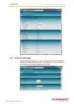
13.3 General setup page
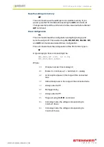
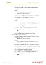
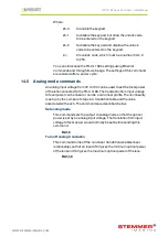
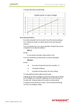
On the general setup page, you can set a password for the TR-CL180 and
send it commands. Refer to
Section 14, Configuration commands
for the
commands you can use to operate the TR-CL180.
—
26
—
TR-CL180 Lens Controller - User Manual
14
Configuration commands
In addition to configuring the TR-CL180 using its web page interface, you
can configure it using the Ethernet or RS232 connections. Both of these
methods are described in this section.
14.1 Ethernet configuration
You can configure the TR-CL180 through the Ethernet connection using
UDP or TCP/IP. You can download GardasoftMaint from
www.gardasoft.com/downloads, which allows you to send commands to
configure your TR-CL180.
Commands sent in UDP or TCP/IP from a computer to the TR-
CL180must be sent to destination port 30313. Replies to the source port
have the source port and destination port identities exchanged.
TCP/IP connections time out and close if they remain idle for more than 10
seconds. The host must send regular commands or ‘keep alive’ packets of
data to keep the connection open.
A carriage return (ASCII 13) character must be sent to terminate the
command line in case multiple TCP packets become joined.
14.2 RS232 configuration
When using RS232 to configure the TR-CL180, the COM port should be
set to 115200baud, 8 data bits, no parity, 1 stop bit, no handshaking.
A carriage return (ASCII 13) character should be sent to terminate the
command line.
14.3 Command structure
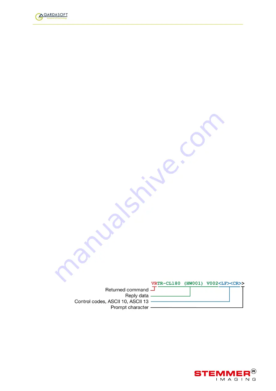
Commands are sent by the host (a PC connected to the network). The
command is returned by the TR-CL180, together with any reply generated
by that command, in UDP or TCP/IP packets followed by
<LF> <CR>
.
The last character sent is the
>
prompt. Once this has been received, the
host knows the command has been completed.
For example, sending the
VR
command might get this reply:
—
27
—
WWW.STEMMER-IMAGING.COM

