TR-CL180 Lens Controller - User Manual
9
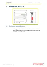
Connecting the TR-CL180
Refer to
Section 15.1, Specifications and ratings
for the ratings of the
connections. The TR-CL180’s connections are shown below:
9.1
Power
Any power supply derived from mains electricity must have a Safety Extra
Low Voltage (SELV) output. Route low voltage wiring to the
TR-CL180 controller separately from mains electricity wiring.
If this is not possible, make sure the low voltage wiring has an insulation
rating that is appropriate or supplementary insulation is used. The
connections are shown below:
—
10
—
TR-CL180 Lens Controller - User Manual
9.2
Lens output
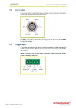
The lens output is the standard 6-way Hirose connector used on Optotune
lenses. The connections are shown below:
The
SCL
connection provides the clocking pulses to the lens, and the
SDA
connection is data.
9.3
Trigger input
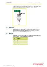
The trigger input is a Smart Input; it accepts a range of trigger sources with
minimal extra circuitry. Refer to
Section 10, General description
for further
information.
Note:
The Smart Input is not isolated, it is ground referenced to the power
supply negative connection.
—
11
—
WWW.STEMMER-IMAGING.COM


