TR-CL180 Lens Controller - User Manual
10
General description
Three modes of operation are provided for the lens output:
Continuous
– the output is constant, and can be set to any value
between the minimum and maximum optical power of the lens.
Switch
– the trigger input can be used to switch the output between an
active optical power value and an idle optical power value.
Analog
- the output is controlled by an analogue signal on the trigger input
which can vary the optical power between the minimum and maximum
power of the lens.
Additionally, using configuration commands, you can select a range of
waveforms to output (see
Section 14.6, Waveform commands
), and
program a timed sequence of optical power settings (see
Section 14.7,
Programmable step commands
).
The set-up is non-volatile, so the TR-CL180 resumes the same operation
after a power cycle.
10.1 Triggering
Trigger pulses should have a minimum pulse width of 2µs. You can set the
sense of the TR-CL180 trigger input. Do this by setting the P flag from the
front panel (see
Section 14, Configuration commands
), the web page (see
Section 13, Webpage configuration
) or the
RE command (see
Section 14,
Configuration commands
). The effect of setting the P flag is summarised
below:
Mode
P Flag
Output
Continuous
Unused
Output is on.
Switched
P Flag = 1
Output is
Idle when trigger is off,
Output is
Active when trigger is on.
P Flag = 0
Output is
Active when trigger is off,
Output is
Idle when trigger is on.
Analog
Unused
N/A.
Note:
The P flag inverts the sense of the trigger.
—
14
—
TR-CL180 Lens Controller - User Manual
10.1.1 Trigger input options
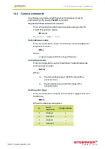
You can connect the following types of trigger to the Smart Input:
3V to 24V voltage source
Any voltage between 0V and 0.9V
is taken as logic 0.
Any voltage between 3V and 24V
is taken as logic 1.
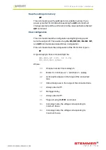
TTL signal
You can connect a TTL signal to
the TR-CL180 input. However, a
3.3V TTL signal only works if it can
drive 8kohm without dropping
below 2.7V.
If the P flag is set to ‘1’, the TR-
CL180 output turns on when the
TTL driver goes HIGH. To reverse
this, set the P flag to ‘0’ (see
Section 10.1, Triggering
).
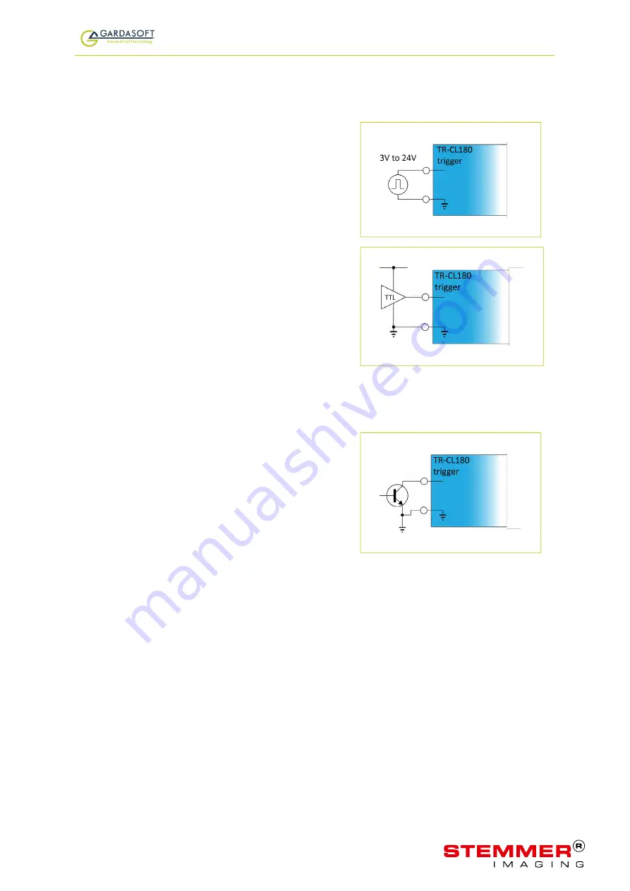
NPN signal
You can connect an NPN open
collector drive to the TR-CL180’s
input. Use the connections
shown opposite.
If the P flag is set to ‘1’ the TR-
CL180 output turns on when the
driving transistor turns on. To
reverse this, set the P flag to ‘0’.
(see
Section 10.1, Triggering
).
—
15
—
WWW.STEMMER-IMAGING.COM


