


RS232 - Main Port {P1} DATATERM
1 No Connect
6 No Connect
2 Transmit Data - output
7 Clear To Send - input
3 Receive Data - input
8 Request To Send - output
4 No Connect
9 No connect
5 Ground
RS232 - Auxiliary Port {P2} DATASET
1 No Connect
6 No Connect
2 Receive Data - input
7 Request To Send - output
3 Transmit Data - output
8 Clear To Send - input
4 No Connect
9 No Connect (Can be connected to 5V with APWR jumper)
5 Ground
Configuration
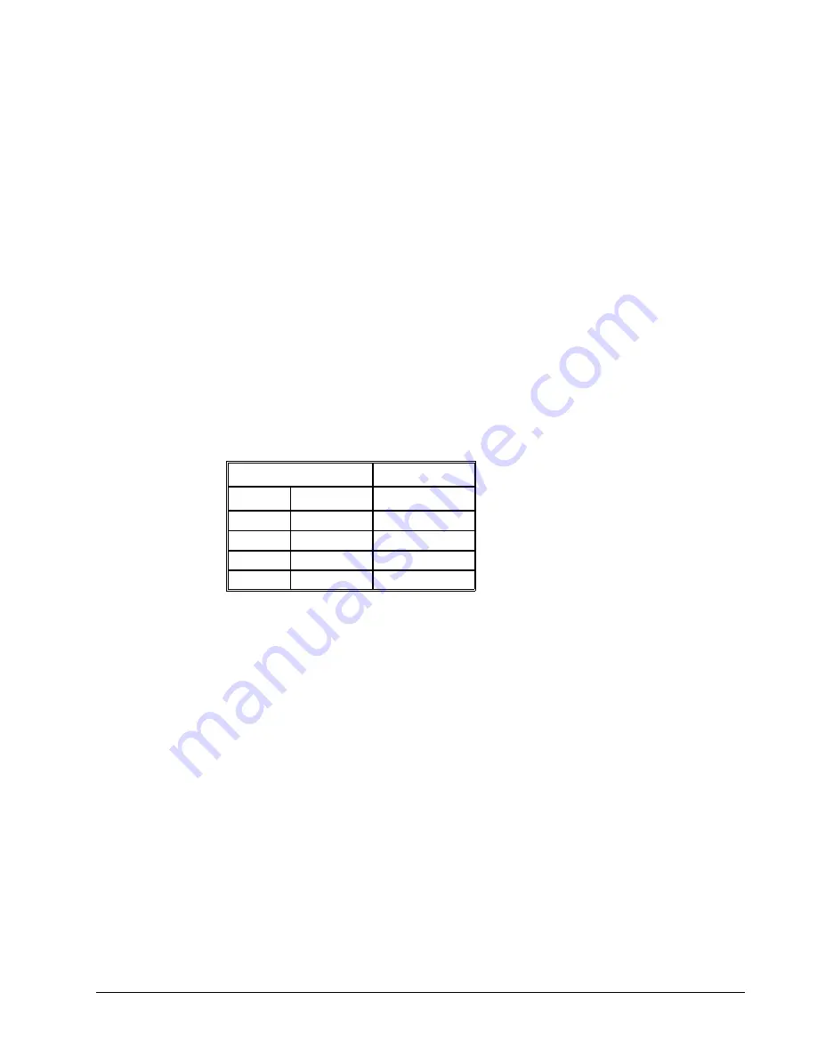
Configure your PC for 8-bit data, one start-bit, one stop-bit, full duplex and no parity. The baud rate for the RS232
communication can be selected by setting the proper switch configuration on the front panel according to the table
below.
Baud Rate Selection
SWITCH SETTINGS
19.2
38.4
BAUD RATE
ON
ON
9600
ON
OFF
19200
OFF
ON
38400
OFF
OFF
115200
Handshaking
The RS232 main port is set for hardware handshaking. Hardware Handshaking uses the RTS and CTS lines. The
CTS line will go high whenever the DMC-40x0 is not ready to receive additional characters. The RTS line will
inhibit the DMC-40x0 from sending additional characters. Note, the RTS line goes high for inhibit.
The auxiliary port of the DMC-40x0 can be configured either as a general port or for the daisy-chain. When
configured as a general port, the port can be commanded to send ASCII messages to another DMC-40x0 controller
or to a display terminal or panel.
CC Command:
(Configure Communication) at port 2. The command is in the format of (See CC in the Command
Reference for more information):
CC m,n,r,p
where ‘m’ sets the baud rate, ‘n’ sets for either handshake or non-handshake mode, ‘r’ sets for general
port or the auxiliary port, and ‘p’ turns echo on or off.
m - Baud Rate – 9600,19200,38400,115200
n - Handshake - 0=No; 1=Yes
r - Mode - 0=Disabled; 1=enabled
p - Echo - 0=Off; 1=On; Valid only if r=0
NOTE:
for the handshake of the auxiliary port, the roles for the RTS and CTS lines are reversed.
Chapter 4 Software Tools and Communication
•
49
DMC-40x0 User Manual
Содержание DMC-4040
Страница 17: ...DMC 4080 Layout Figure 2 2 Outline of the of the DMC 4080 DMC 40x0 User Manual Chapter 2 Getting Started 8...
Страница 19: ...DMC 4040 Dimensions Figure 2 5 Dimensions of DMC 4040 DMC 40x0 User Manual Chapter 2 Getting Started 10...
Страница 20: ...DMC 4080 Dimensions Figure 2 6 Dimensions of DMC 4080 Chapter 2 Getting Started 11 DMC 40x0 User Manual...
Страница 54: ...Chapter 3 Connecting Hardware 45 DMC 40x0 User Manual...
Страница 55: ...DMC 40x0 User Manual Chapter 3 Connecting Hardware 46...
Страница 56: ...Chapter 3 Connecting Hardware 47 DMC 40x0 User Manual...
Страница 73: ...Figure 4 1 GalilTools DMC 40x0 User Manual Chapter 4 Software Tools and Communication 64...
Страница 185: ...THIS PAGE LEFT BLANK INTENTIONALLY DMC 40x0 User Manual Chapter 7 Application Programming 176...
Страница 205: ...THIS PAGE LEFT BLANK INTENTIONALLY DMC 40x0 User Manual Chapter 10 Theory of Operation 196...
Страница 220: ...Step 2 Remove ICM For DMC 4040 Proceed to Step 3 Configure Circuit Appendices 211 DMC 40x0 User Manual...
Страница 222: ...Step 2 Remove ICM s Appendices 213 DMC 40x0 User Manual...
Страница 232: ...DMC 4080 Steps 4 and 5 Step 4 Replace ICM s Appendices 223 DMC 40x0 User Manual...


