M
CB
3
Installation Manual
Page 13
System Components
Control Box
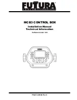
The control box mounts in the cab and is cable connected to machine power, the
MCR
receivers and the hydraulic valve. Optional remote switches may also be connected. The operator
adjusts and selects various options using toggle switches or multi-switches that move left/right,
up/down, rotate in both directions, and can be pushed in.
An LCD indicates system and configuration status. An LED display indicates grade information for
each side. Automatic or manual modes are also indicated with LED's for each side.
Refer to the control box operator's manual (P/N ATI-010884) for detailed operational information.
The Control Box should be mounted in a location that is easily visible to the operator, is within easy
reach of the operator’s hands, and can be easily installed and removed. Insure that the location does
not interfere with other machine controls or operator movements. Remote switches are available which
allow the operator to adjust the system while keeping hands on the machine controls.
The Control Box has vented drain holes on the rear bottom of the unit that must
face downward.
A control box mounting bracket (ATI-950054) is designed to accept the mounting
knobs that are included with the control box.
0&5
Receivers
All
MCR
receivers feature 360 degree laser reception and work with all common rotating lasers.
MCR
models
1
,
2
, MC
2E
, and
3
are designed for automatic blade control and will work with
the
M
CB
3
. The model
1
has limited proportional control capability and therefore limited on-grade
offset and elevation matching capability.
Models
2
and
3
incorporate internal slope sensors that can be used for blade slope control.
NOTE:
These slope sensors must be calibrated to the machine before use.
Models
1
,
2
and
3
can also be used as stand alone display receivers.
Please refer to the specific
MCR
operator's manuals for more detailed information.
The
MCR
receivers mount to round masts from sizes 1.66” to 2.00” O.D. (42 to 50 mm) and to
1-1/2” (38 mm) square tube.
The communication protocol for the
MCR
receivers is proprietary RS485 @ 62.5 kbaud.
General Installation
4.1
Содержание MCB3
Страница 1: ...MCB3 CONTROL BOX Installation Manual Technical Information Software Version 3 00 P N ATI 026046 Rev C...
Страница 57: ...MCB3 Installation Manual Page 55 NOTES...
Страница 58: ...MCB3 Installation Manual Page 56 NOTES...
Страница 59: ...Page 57 NOTES MCB3 Installation Manual...
Страница 60: ...Futtura Tools Technologies Inc 100 N Rockwell Ste 96 Oklahoma City OK 73127 USA...


