C156-E097-01EN
3 - 11
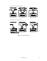
The Frame Ground is shorted in the optical disk drive by a metal strip attached to the vibration
isolation rubber between the frame (FG) and the base (SG).
3.3
Power Supply Requirements
(1)
Allowable input voltage and current
The DC power supply input voltage measured at the power supply connector pin of the optical
disk drive (receiving end) must satisfy the requirements in Section 2.1.3. (For other
requirements, see items (4) and (5) below.)
(2)
Current waveform (reference)
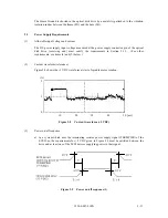
Figure 3.8 shows the +5 VDC waveform at start of spindle motor rotation.
Figure 3.8
Current waveform (+5 VDC)
(3)
Power on/off sequence
a) In a system which uses the terminating resistor power supply signal (TERMPWR) of the
SCSI bus, the requirements for +5 VDC given in Figure 3.9 must be satisfied between the
drive and at least one of the SCSI devices supplying power to that signal.
Figure 3.9
Power on/off sequence (1)
[ms]
50
40
30
20
10
0
1
(A)
2
Содержание MCE3064SS
Страница 1: ...C156 E097 01EN MCE3064SS MCF3064SS OPTICAL DISK DRIVES PRODUCT MANUAL ...
Страница 3: ...This page is intentionally left blank ...
Страница 31: ...This page is intentionally left blank ...
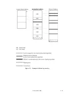
Страница 52: ...C156 E097 01EN 2 21 Figure 2 3 Example of alternate processing ...
Страница 53: ...This page is intentionally left blank ...
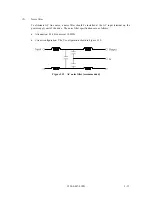
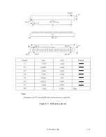
Страница 72: ...C156 E097 01EN 3 19 Figure 3 17 SCSI cable connector ...
Страница 81: ...This page is intentionally left blank ...
Страница 97: ...4 16 C156 E097 01EN Figure 4 5 SCSI connection check 2 ...
Страница 99: ...This page is intentionally left blank ...
Страница 113: ...This page is intentinally left blank ...
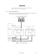
Страница 119: ...7 2 C156 E097 01EN Host system A Host system B Figure 7 1 Example of SCSI configuration ...
Страница 133: ...7 16 C156 E097 01EN Figure 7 6 ARBITRATION phase ...
Страница 135: ...7 18 C156 E097 01EN µ Figure 7 7 SELECTION phase 30 30 30 30 ...
Страница 141: ...7 24 C156 E097 01EN Figure 7 10 Transfer in asynchronous mode 18 18 ...
Страница 145: ...7 28 C156 E097 01EN Figure 7 11 Transfer in synchronous mode 11 11 11 11 43 18 43 18 ...
Страница 146: ...C156 E097 01EN 7 29 Figure 7 12 Transfer in FAST SCSI mode ...
Страница 148: ...C156 E097 01EN 7 31 Figure 7 13 Data transfer rate in asynchronous mode ...
Страница 158: ...C156 E097 01EN 7 41 Figure 7 17 RESET condition ...
Страница 160: ...C156 E097 01EN 7 43 Figure 7 18 Bus phase sequence 1 of 2 ...
Страница 161: ...7 44 C156 E097 01EN Figure 7 18 Bus phase sequence 2 of 2 ...
Страница 162: ...C156 E097 01EN 7 45 Figure 7 19 Example of bus phase transition on execution of a single command 1 of 5 ...
Страница 163: ...7 46 C156 E097 01EN Figure 7 19 Example of bus phase transition on execution of a single command 2 of 5 ...
Страница 164: ...C156 E097 01EN 7 47 Figure 7 19 Example of bus phase transition on execution of a single command 3 of 5 ...
Страница 165: ...7 48 C156 E097 01EN Figure 7 19 Example of bus phase transition on execution of a single command 4 of 5 ...
Страница 166: ...C156 E097 01EN 7 49 Figure 7 19 Example of bus phase transition on execution of a single command 5 of 5 ...
Страница 167: ...This page is intentionally left blank ...
Страница 171: ...This page is intentionally left blank ...
Страница 181: ......

