C156-E097-01EN
GL - 1
Glossary
Error detection and correction
A series of methods are used to append
redundancy to data in a known format and to
record data. The decoder removes the
redundancy when the data is read. The
redundancy information is used for error
detection and correction.
Error correction code
Error detection code designed to correct certain
types of error in data.
Initiator (INIT)
An SCSI device that activated an input-output
operation on an SCSI bus. In this manual, an
initiator may be abbreviated to INIT.
Interleave
A process to sort the physical sequence of data
units so that the data can withstand burst errors
better.
Recording layer
A layer in the disk where data is recorded
during manufacture and during writing.
Recording power
The defined power of incidence for the incident
surface used to form marks.
Clamped area
The ring section of the disk where clamp force
is applied by the clamp mechanism.
Defect management
Defect management is done by an automatic
real-time program. The program changes the
read and write power, focus, and tracking when
an error is detected. The program also
determines whether to discard a sector that
contains many errors. In batch mode, defect
management is a guideline for disk rerecording
and saving.
Disk case
A case that covers the optical disk. The case
protects the disk from damage during handling
and makes it possible to replace disks. The case
has space for a label, write-protection notch,
automatic handling preparation, and medium
identification hole.
Command
An input-output instruction for the target
described in the CDB.
Control track
Track used for medium parameters and format
information required for writing and reading the
optical disk.
LUN (Logical Unit Number)
A device address used to identify a logical unit.
Acceleration in the axis direction
Acceleration to the defined rotation speed in
the recording layer along a straight line
perpendicular to the disk reference surface.
Detected optically.
Displacement of axis direction
Displacement of a point from the standard
position in the recording layer perpendicular to
the disk reference surface. The standard
position is detected optically by measuring the
protective layer thickness and refractive index
based on the disk reference surface.
Status
One-byte information that indicates the
command termination state. Reported by the
target to the initiator when execution of a
command ends.
Содержание MCE3064SS
Страница 1: ...C156 E097 01EN MCE3064SS MCF3064SS OPTICAL DISK DRIVES PRODUCT MANUAL ...
Страница 3: ...This page is intentionally left blank ...
Страница 31: ...This page is intentionally left blank ...
Страница 52: ...C156 E097 01EN 2 21 Figure 2 3 Example of alternate processing ...
Страница 53: ...This page is intentionally left blank ...
Страница 72: ...C156 E097 01EN 3 19 Figure 3 17 SCSI cable connector ...
Страница 81: ...This page is intentionally left blank ...
Страница 97: ...4 16 C156 E097 01EN Figure 4 5 SCSI connection check 2 ...
Страница 99: ...This page is intentionally left blank ...
Страница 113: ...This page is intentinally left blank ...
Страница 119: ...7 2 C156 E097 01EN Host system A Host system B Figure 7 1 Example of SCSI configuration ...
Страница 133: ...7 16 C156 E097 01EN Figure 7 6 ARBITRATION phase ...
Страница 135: ...7 18 C156 E097 01EN µ Figure 7 7 SELECTION phase 30 30 30 30 ...
Страница 141: ...7 24 C156 E097 01EN Figure 7 10 Transfer in asynchronous mode 18 18 ...
Страница 145: ...7 28 C156 E097 01EN Figure 7 11 Transfer in synchronous mode 11 11 11 11 43 18 43 18 ...
Страница 146: ...C156 E097 01EN 7 29 Figure 7 12 Transfer in FAST SCSI mode ...
Страница 148: ...C156 E097 01EN 7 31 Figure 7 13 Data transfer rate in asynchronous mode ...
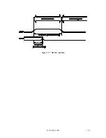
Страница 158: ...C156 E097 01EN 7 41 Figure 7 17 RESET condition ...
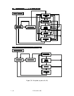
Страница 160: ...C156 E097 01EN 7 43 Figure 7 18 Bus phase sequence 1 of 2 ...
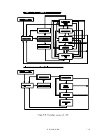
Страница 161: ...7 44 C156 E097 01EN Figure 7 18 Bus phase sequence 2 of 2 ...
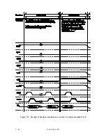
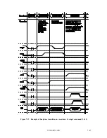
Страница 162: ...C156 E097 01EN 7 45 Figure 7 19 Example of bus phase transition on execution of a single command 1 of 5 ...
Страница 163: ...7 46 C156 E097 01EN Figure 7 19 Example of bus phase transition on execution of a single command 2 of 5 ...
Страница 164: ...C156 E097 01EN 7 47 Figure 7 19 Example of bus phase transition on execution of a single command 3 of 5 ...
Страница 165: ...7 48 C156 E097 01EN Figure 7 19 Example of bus phase transition on execution of a single command 4 of 5 ...
Страница 166: ...C156 E097 01EN 7 49 Figure 7 19 Example of bus phase transition on execution of a single command 5 of 5 ...
Страница 167: ...This page is intentionally left blank ...
Страница 171: ...This page is intentionally left blank ...
Страница 181: ......

