3 - 12
C156-E097-01EN
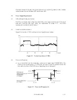
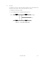
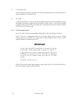
b) In a system which does not use the terminating resistor power supply signal (TERMPWR) of
the SCSI bus, the requirements for +5 VDC given in Figure 3.10 must be satisfied between
the drive and the SCSI device with the terminating resistor circuit.
Figure 3.10 Power on/off sequence (2)
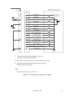
c) Between the drive and other SCSI devices on the SCSI bus, the +5 VDC power on/off
sequence is as follows:
•
In a system with all its SCSI devices designed to prevent noise leakage to the SCSI bus
when the power is turned on or off, the power sequence does not matter if the
requirement in (a) or (b) is satisfied.
•
In a system containing an SCSI device which is not designed to prevent noise leakage to
the SCSI bus, the requirement given in Figure 3.11 must be satisfied between the SCSI
device and the drive.
Figure 3.11 Power on/off sequence (3)
(4)
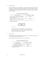
Power supply to SCSI terminating resistor
If the power for the terminating resistor is supplied from the drive to other SCSI devices through
the SCSI bus, the current-carrying capacity of the +5 VDC power supply line to the optical disk
drive must be designed with consideration of an increase of up to 900 mA.
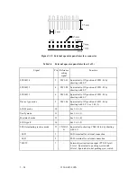
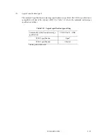
Select a method of power supply to the drive in accordance with the setting terminal of the
optical disk drive. See Subsection 4.3.3.
0.5V
4.75V
0.5V
4.75V
Содержание MCE3064SS
Страница 1: ...C156 E097 01EN MCE3064SS MCF3064SS OPTICAL DISK DRIVES PRODUCT MANUAL ...
Страница 3: ...This page is intentionally left blank ...
Страница 31: ...This page is intentionally left blank ...
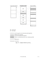
Страница 52: ...C156 E097 01EN 2 21 Figure 2 3 Example of alternate processing ...
Страница 53: ...This page is intentionally left blank ...
Страница 72: ...C156 E097 01EN 3 19 Figure 3 17 SCSI cable connector ...
Страница 81: ...This page is intentionally left blank ...
Страница 97: ...4 16 C156 E097 01EN Figure 4 5 SCSI connection check 2 ...
Страница 99: ...This page is intentionally left blank ...
Страница 113: ...This page is intentinally left blank ...
Страница 119: ...7 2 C156 E097 01EN Host system A Host system B Figure 7 1 Example of SCSI configuration ...
Страница 133: ...7 16 C156 E097 01EN Figure 7 6 ARBITRATION phase ...
Страница 135: ...7 18 C156 E097 01EN µ Figure 7 7 SELECTION phase 30 30 30 30 ...
Страница 141: ...7 24 C156 E097 01EN Figure 7 10 Transfer in asynchronous mode 18 18 ...
Страница 145: ...7 28 C156 E097 01EN Figure 7 11 Transfer in synchronous mode 11 11 11 11 43 18 43 18 ...
Страница 146: ...C156 E097 01EN 7 29 Figure 7 12 Transfer in FAST SCSI mode ...
Страница 148: ...C156 E097 01EN 7 31 Figure 7 13 Data transfer rate in asynchronous mode ...
Страница 158: ...C156 E097 01EN 7 41 Figure 7 17 RESET condition ...
Страница 160: ...C156 E097 01EN 7 43 Figure 7 18 Bus phase sequence 1 of 2 ...
Страница 161: ...7 44 C156 E097 01EN Figure 7 18 Bus phase sequence 2 of 2 ...
Страница 162: ...C156 E097 01EN 7 45 Figure 7 19 Example of bus phase transition on execution of a single command 1 of 5 ...
Страница 163: ...7 46 C156 E097 01EN Figure 7 19 Example of bus phase transition on execution of a single command 2 of 5 ...
Страница 164: ...C156 E097 01EN 7 47 Figure 7 19 Example of bus phase transition on execution of a single command 3 of 5 ...
Страница 165: ...7 48 C156 E097 01EN Figure 7 19 Example of bus phase transition on execution of a single command 4 of 5 ...
Страница 166: ...C156 E097 01EN 7 49 Figure 7 19 Example of bus phase transition on execution of a single command 5 of 5 ...
Страница 167: ...This page is intentionally left blank ...
Страница 171: ...This page is intentionally left blank ...
Страница 181: ......

