03-05
3-2-3 "COOL" Position
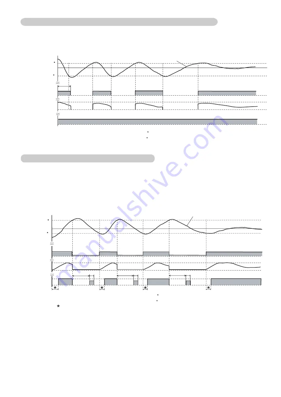
An example for COOLING TEMPERATURE CONTROL time chart (Manual setting)
When using the cooling mode, set the temperature to a value lower than the current room temperature
, otherwise
the indoor unit will not start the cooling operation and only the fan will rotate.
• Indoor fan
Ts
• Opening of
EEV
100%
0%
• Refrigerant
flow
ON
OFF
ON
OFF
• Temperature
Ts + 0.5 C
T
R
3Min.
Ts : Corrected setting temperature
T
R
: Corrected room temperature
: The thres hold temperature of start of refrigrant flow
: The thres hold temperature of stop of refrigrant flow
Ts - 0.5 C
Ts + 0.5 C
Ts - 0.5 C
Ts + 0.5 C
Ts - 0.5 C
: The thres hold temperature of start of refrigrant flow
: The thres hold temperature of stop of refrigrant flow
Ts + 0.5 C
Ts - 0.5 C
3-2-4 "HEAT" Position
(1) When using the heating mode, set the temperature to a value higher than the current room temperature
, otherwise
the indoor unit will not start the heating operation.
(3)
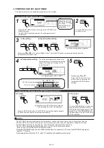
An example for HEATING TEMPERATURE CONTROL time chart (Manual setting)
During defrosting, the OPERATION indicator lamp flashes 6 sec. ON and 2 sec. OFF, and repeat. The heating operation
will be temporarily interrupted.
• Indoor fan
Ts
• Opening of
EEV
100%
0%
• Refrigerant
flow
ON
OFF
ON
OFF
• Temperature
T
R
4Min. 1Min.
4Min. 1Min.
4Min. 1Min.
Ts : Corrected setting temperature
T
R
: Corrected room temperature
: Duration of cold air prevention
(2) After the start of heating operation, the fan of indoor unit will not rotate until the heater exchange is warmed up to
blow out warm air.
Содержание Airstage J-II
Страница 1: ...Small VRF system for light commercial and home use SERVICE MANUAL ...
Страница 2: ......
Страница 6: ......
Страница 7: ...1 TEST RUN ...
Страница 8: ......
Страница 27: ...2 OUTDOOR UNIT OPERATION CONTROL ...
Страница 28: ......
Страница 42: ......
Страница 43: ...3 INDOOR UNIT OPERATION ...
Страница 44: ......
Страница 63: ...4 TROUBLE SHOOTING ...
Страница 73: ......
Страница 170: ......
Страница 171: ...5 APPENDING DATA UNIT ...
Страница 172: ......
Страница 174: ...MODELS AUXB07 AUXB09 AUXB12 AUXB14 AUXB18 AUXB24 05 02 5 2 WIRING DIAGRAM 5 2 1 Indoor Unit ...
Страница 175: ...MODELS AUXD18 AUXD24 AUXA30 AUXA36 AUXA45 AUXA54 05 03 ...
Страница 176: ...MODELS ARXB07 ARXB09 ARXB12 ARXB14 ARXB18 05 04 ...
Страница 177: ...MODEL ARXB24 MODELS ARXB30 ARXB36 05 05 ...
Страница 178: ...MODEL ARXB45 05 06 ...
Страница 179: ...MODEL ARXA24 MODELS ARXA30 ARXA36 ARXA45 05 07 ...
Страница 180: ...MODELS ARXC36 ARXC45 ARXC60 MODELS ARXC72 ARXC90 05 08 ...
Страница 181: ...MODELS ARXD07 ARXD09 ARXD12 ARXD14 ARXD18 ARXD24 05 09 ...
Страница 182: ...MODELS AB A12 AB A14 AB A18 AB A24 05 10 ...
Страница 183: ...MODELS AB A12LBTH AB A14LBTH 05 11 AB A18LBTH AB A24LBTH ...
Страница 184: ...05 12 MODELS AB A30 AB A36 AB A45 AB A54 ...
Страница 185: ...05 13 MODELS AB A30LBTH AB A36LBTH AB A45LBTH AB A54LBTH ...
Страница 186: ...MODELS AS A07 AS A09 AS A12 AS A14 05 14 ...
Страница 187: ...MODELS AS E07 AS E09 AS E12 AS E14 05 15 ...
Страница 188: ...MODELS AS A18 AS A24 AS A30 05 16 ...
Страница 189: ...05 17 MODELS AS A18LACH AS A24LACH AS A30LACH ...
Страница 190: ...05 18 MODELS AJ A36 45 54LALH 5 2 2 Outdoor Unit ...
Страница 195: ...6 DISASSEMBLY PROCESS ...
Страница 196: ......


