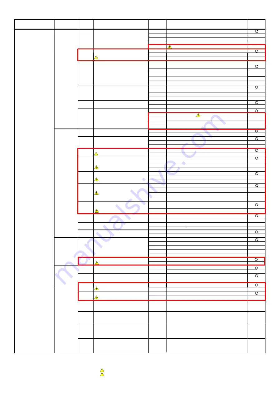
Setting Mode
ITEM
CODE No.
Setting Function
Default
Install
00
Pipe length setting
00
40-65m
Setting mode
01
0-40m
02
65-90m
03
90-120m
04
Correction
10
Sequential start shift
00
01
02
03
11
Cooling capacity shift
00
Normal mode
01
Save energy mode 1 (+2
°C)
02
High power mode 1 (-2
°C)
03
High power mode 2 (-4
°C)
12
Heating capacity shift
00
Normal mode
01
Save energy mode (-2
°C)
02
High power mode 1 (+2
°C)
03
High power mode 2 (+4
°C)
13
Defrost setting shift
00
End temperature:Normal
01
End temperature:Higher
01
Emergency stop
21
Operation mode selecting method
00
Priority given to the first command
01
Priority given to the external input of outdoor unit
02
Priority given to the master indoor unit
22
Snow falling protection fan mode
00
Normal operation
01
23
Interval setting for snow falling
00
Standard
01
02
03
24
High static pressure mode
00
Standard
01
02
28
Change of unit (Temperature)
00
Celsius(
°C)
01
Fahrenheit ( F)
29
Change of unit (Pressure)
00
MPa
01
psi
Change of
Change of
function 3
30
Energy saving level setting
00
Level 1 (stop)
01
Level 2 (operated at 40% capacity)
02
Level 3 (operated at 60% capacity)
03
Level 4 (operated at 80% capacity)
04
Level 5 (operated at 100% capacity)
Low noise
40
Capacity priority setting
00
Off (quiet priority)
01
On (capacity priority)
41
Low noise mode setting
00
Off (Normal)
60
Back up operation
00
Standard
01
01
On (Low noise mode operation is always done)
42
Low noise mode operation level
00
Standard (47dB)
01
[ F2 ]
ITEM
CODE No.
Standard
20
Switching between forced stop or
00
Forced stop
Change of
function 1
emergency stop
protection fan mode
setting 1
(in low noise mode)
function 2
Classification
01-16
Push switch
on outdoor unit PCB
Setting is forbidden
Setting is forbidden
Setting is forbidden
Setting is forbidden
70
Electricity meter No. setting 1
(Set the ones digit and tens digit of the No of
the electricity meter connected to CN135.) *3
00~99
Setting number x00~x99
00
71
Electricity meter No. setting 2
(Set the hundreds digit of the No. of the
electricity meter connected to CN135.) *3
00~02
Setting number 0xx~2xx
00
72
Electricity meter pulse setting 1
(Set the ones digit and tens digit of the No. of
the electricity meter pulse setting connected
to CN135.) *4
00~99
Setting number xx00~xx99
00
73
Electricity meter pulse setting 2
(Set the hundreds digit and thousands digit
of the electricity meter pulse setting connected
to CN135.) *4
00~99
Setting number 00xx~99xx
00
Change of
function 4
*3 : When electricity meter No. is set to "000" and "201 to 299", the pulses input to CN135 become ineffective.
Available setting number is "001" to "200"
*4 : When the electricity meter pulse setting is set to "0000", the pulses input to CN135 become ineffective.
Available setting number is "0001" to "9999"
( Refer to Design & Technical Manual for details.)
( Refer to Design & Technical Manual for details.)
( Refer to Design & Technical Manual for details.)
( Refer to Design & Technical Manual for details.)
Setting is forbidden: Any of problems caused by changing these setting is not covered by the warranty.
14
Pressure equalization time shift
before defrosting start
00
No time shift
01
Shift 1 ( 30 sec.)
02
Shift 2 ( 60 sec.)
03
04
Shift 3 ( 90 sec.)
Shift 3 ( 120 sec.)
Only for solution :
Only when the refrigerant noise during Defrosting was pointed out. It is the case that the
compressor operating time in heating will be shorter.
Only for solution
04
High power mode 3 (-5
°C)
03
Oil recovery
00
02
Setting is forbidden
01
25
Oil recovery Abnormal
low pressure protection control
00
01
26
27
Error code Notification
00
01
Enable
Disable
31
Heating Starting prosess
00
01
Standard
Standard
Standard
Setting is forbidden
Setting is forbidden
Setting is forbidden
Setting is forbidden
Setting is forbidden
Содержание Airstage J-II
Страница 1: ...Small VRF system for light commercial and home use SERVICE MANUAL ...
Страница 2: ......
Страница 6: ......
Страница 7: ...1 TEST RUN ...
Страница 8: ......
Страница 27: ...2 OUTDOOR UNIT OPERATION CONTROL ...
Страница 28: ......
Страница 42: ......
Страница 43: ...3 INDOOR UNIT OPERATION ...
Страница 44: ......
Страница 63: ...4 TROUBLE SHOOTING ...
Страница 73: ......
Страница 170: ......
Страница 171: ...5 APPENDING DATA UNIT ...
Страница 172: ......
Страница 174: ...MODELS AUXB07 AUXB09 AUXB12 AUXB14 AUXB18 AUXB24 05 02 5 2 WIRING DIAGRAM 5 2 1 Indoor Unit ...
Страница 175: ...MODELS AUXD18 AUXD24 AUXA30 AUXA36 AUXA45 AUXA54 05 03 ...
Страница 176: ...MODELS ARXB07 ARXB09 ARXB12 ARXB14 ARXB18 05 04 ...
Страница 177: ...MODEL ARXB24 MODELS ARXB30 ARXB36 05 05 ...
Страница 178: ...MODEL ARXB45 05 06 ...
Страница 179: ...MODEL ARXA24 MODELS ARXA30 ARXA36 ARXA45 05 07 ...
Страница 180: ...MODELS ARXC36 ARXC45 ARXC60 MODELS ARXC72 ARXC90 05 08 ...
Страница 181: ...MODELS ARXD07 ARXD09 ARXD12 ARXD14 ARXD18 ARXD24 05 09 ...
Страница 182: ...MODELS AB A12 AB A14 AB A18 AB A24 05 10 ...
Страница 183: ...MODELS AB A12LBTH AB A14LBTH 05 11 AB A18LBTH AB A24LBTH ...
Страница 184: ...05 12 MODELS AB A30 AB A36 AB A45 AB A54 ...
Страница 185: ...05 13 MODELS AB A30LBTH AB A36LBTH AB A45LBTH AB A54LBTH ...
Страница 186: ...MODELS AS A07 AS A09 AS A12 AS A14 05 14 ...
Страница 187: ...MODELS AS E07 AS E09 AS E12 AS E14 05 15 ...
Страница 188: ...MODELS AS A18 AS A24 AS A30 05 16 ...
Страница 189: ...05 17 MODELS AS A18LACH AS A24LACH AS A30LACH ...
Страница 190: ...05 18 MODELS AJ A36 45 54LALH 5 2 2 Outdoor Unit ...
Страница 195: ...6 DISASSEMBLY PROCESS ...
Страница 196: ......


