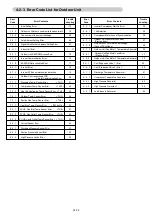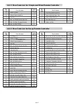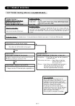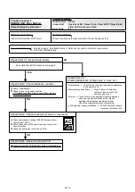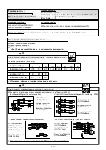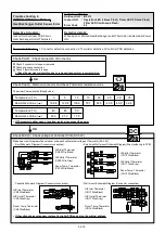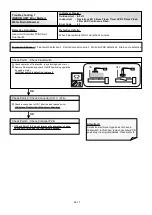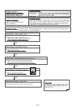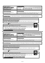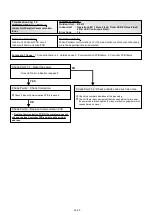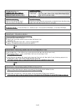
(1)
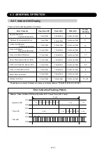
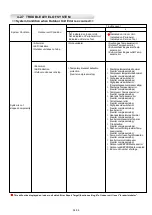
Not indicated on Indoor Unit.
Not indicated on Peripheral Unit.
Indicated on Service Tool.
(2)
Indicated on Indoor Unit.
Indicated on Peripheral.
Indicated on Service Tool.
- Discharge temperature abnormal
- Compressor temperature abnormal
- Current sensor error
- Inverter compressor start up error
- Trip detection
- Rush current limiting resister Temp rise protection
-
Comp. motor loss of synchronization
- Low pressure abnormal
- Fan motor 1 lock error
- Fan motor 2 lock error
System Condition
Outdoor unit Condition
System is
compulsorily stopped.
Even if power is reset, the following Error cannot release.
<Important>
These errors can not be judged without operating the system, and the serviceman
would not be able to check it if the system power is turned off before visiting the site for repair.
In Error release, you need to operate push switch and apply "Error reset" (F3-40) after power restart.
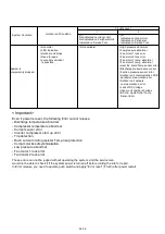
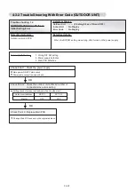
Trouble Level
1
2
>Abnormal
>LED indication
>Outdoor unit stops
>Need to repair
>secondary accident
is possible.
(Not available)
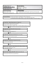
>High pressure abnormal
>Low pressure abnormal
>Fan motor 1 lock error
>Fan motor 2 lock error
>Fan motor 1 temp. abnormal
>Fan motor 2 temp. abnormal
>Heat Ex. liquid Temp sensor error
>Discharge pressure sensor error
>Suction pressure sensor error
>Outdoor unit communication PCB
parallel communication error
>Outdoor unit network
communication 2 error
>Lack of DC Voltage
>Indoor unit number shortage
>SC HE. Liquid Outlet Temp
Sensor Error
04-09
Содержание Airstage J-II
Страница 1: ...Small VRF system for light commercial and home use SERVICE MANUAL ...
Страница 2: ......
Страница 6: ......
Страница 7: ...1 TEST RUN ...
Страница 8: ......
Страница 27: ...2 OUTDOOR UNIT OPERATION CONTROL ...
Страница 28: ......
Страница 42: ......
Страница 43: ...3 INDOOR UNIT OPERATION ...
Страница 44: ......
Страница 63: ...4 TROUBLE SHOOTING ...
Страница 73: ......
Страница 170: ......
Страница 171: ...5 APPENDING DATA UNIT ...
Страница 172: ......
Страница 174: ...MODELS AUXB07 AUXB09 AUXB12 AUXB14 AUXB18 AUXB24 05 02 5 2 WIRING DIAGRAM 5 2 1 Indoor Unit ...
Страница 175: ...MODELS AUXD18 AUXD24 AUXA30 AUXA36 AUXA45 AUXA54 05 03 ...
Страница 176: ...MODELS ARXB07 ARXB09 ARXB12 ARXB14 ARXB18 05 04 ...
Страница 177: ...MODEL ARXB24 MODELS ARXB30 ARXB36 05 05 ...
Страница 178: ...MODEL ARXB45 05 06 ...
Страница 179: ...MODEL ARXA24 MODELS ARXA30 ARXA36 ARXA45 05 07 ...
Страница 180: ...MODELS ARXC36 ARXC45 ARXC60 MODELS ARXC72 ARXC90 05 08 ...
Страница 181: ...MODELS ARXD07 ARXD09 ARXD12 ARXD14 ARXD18 ARXD24 05 09 ...
Страница 182: ...MODELS AB A12 AB A14 AB A18 AB A24 05 10 ...
Страница 183: ...MODELS AB A12LBTH AB A14LBTH 05 11 AB A18LBTH AB A24LBTH ...
Страница 184: ...05 12 MODELS AB A30 AB A36 AB A45 AB A54 ...
Страница 185: ...05 13 MODELS AB A30LBTH AB A36LBTH AB A45LBTH AB A54LBTH ...
Страница 186: ...MODELS AS A07 AS A09 AS A12 AS A14 05 14 ...
Страница 187: ...MODELS AS E07 AS E09 AS E12 AS E14 05 15 ...
Страница 188: ...MODELS AS A18 AS A24 AS A30 05 16 ...
Страница 189: ...05 17 MODELS AS A18LACH AS A24LACH AS A30LACH ...
Страница 190: ...05 18 MODELS AJ A36 45 54LALH 5 2 2 Outdoor Unit ...
Страница 195: ...6 DISASSEMBLY PROCESS ...
Страница 196: ......


