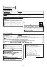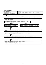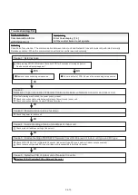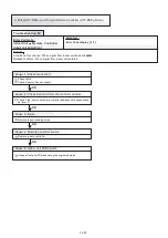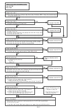
Error Contents :
Transmission Error
Symptom :
Error Code display [ 1 4 ]
OPERATION LED is flashing.
Details :
Condition of occurrence :
When the signal is cut off for more than 10 minutes from the registered Indoor unit (not including Slave unit).
Release condition : 1. The signal has been received from the Indoor units that was creating the error.
2. MPU has been booted up. (Release from the reset operation, the power failure stand-by operation.
Trouble shooting 80
Cause 1 : Connection failure
Check transmission cable
Check disconnected power line for Indoor unit.
Check if convertor power line is disconnected.
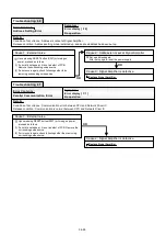
OK
OK
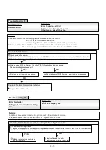
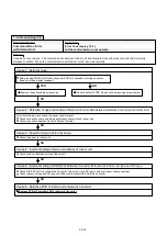
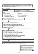
Cause 3 : Remote Controller is defective.
Cause 1 : Remote Controller internal thermistor trouble
Replace Group Remote Controller.
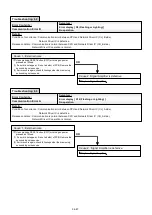
Cause 2 : Check outside cause (Voltage drop or noise, etc.)
Instant drop ----- Check if there is a large load electric apparatus in the same circuit.
Momentary power failure ----- Check if there is a defective contact or leak current in the power supply circuit.
Noise ----- Check if there is any equipment causing harmonic wave near electric line (Neon bulb or electric equipment that may cause
harmonic wave).
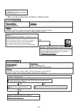
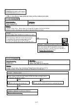
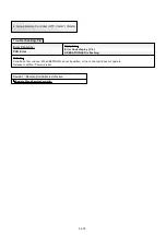
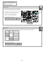
Thermostat Sensor display is flashing.
Cause 1 : Remote controller internal thermistor trouble
Replace remote controller.
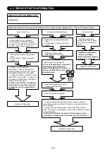
Condition of occurrence : Thermistor in remote controller is open or shorted.
Release condition : Thermistor in remote controller is not open or shorted.
04-79
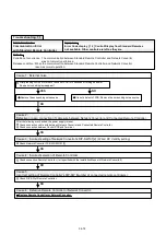
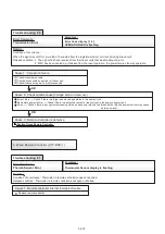
Trouble shooting 81
Error Contents :
Thermo Sensor Error
Symptom :
Details :
5. Wired Remote Controller (UTY-RNK )
Содержание Airstage J-II
Страница 1: ...Small VRF system for light commercial and home use SERVICE MANUAL ...
Страница 2: ......
Страница 6: ......
Страница 7: ...1 TEST RUN ...
Страница 8: ......
Страница 27: ...2 OUTDOOR UNIT OPERATION CONTROL ...
Страница 28: ......
Страница 42: ......
Страница 43: ...3 INDOOR UNIT OPERATION ...
Страница 44: ......
Страница 63: ...4 TROUBLE SHOOTING ...
Страница 73: ......
Страница 170: ......
Страница 171: ...5 APPENDING DATA UNIT ...
Страница 172: ......
Страница 174: ...MODELS AUXB07 AUXB09 AUXB12 AUXB14 AUXB18 AUXB24 05 02 5 2 WIRING DIAGRAM 5 2 1 Indoor Unit ...
Страница 175: ...MODELS AUXD18 AUXD24 AUXA30 AUXA36 AUXA45 AUXA54 05 03 ...
Страница 176: ...MODELS ARXB07 ARXB09 ARXB12 ARXB14 ARXB18 05 04 ...
Страница 177: ...MODEL ARXB24 MODELS ARXB30 ARXB36 05 05 ...
Страница 178: ...MODEL ARXB45 05 06 ...
Страница 179: ...MODEL ARXA24 MODELS ARXA30 ARXA36 ARXA45 05 07 ...
Страница 180: ...MODELS ARXC36 ARXC45 ARXC60 MODELS ARXC72 ARXC90 05 08 ...
Страница 181: ...MODELS ARXD07 ARXD09 ARXD12 ARXD14 ARXD18 ARXD24 05 09 ...
Страница 182: ...MODELS AB A12 AB A14 AB A18 AB A24 05 10 ...
Страница 183: ...MODELS AB A12LBTH AB A14LBTH 05 11 AB A18LBTH AB A24LBTH ...
Страница 184: ...05 12 MODELS AB A30 AB A36 AB A45 AB A54 ...
Страница 185: ...05 13 MODELS AB A30LBTH AB A36LBTH AB A45LBTH AB A54LBTH ...
Страница 186: ...MODELS AS A07 AS A09 AS A12 AS A14 05 14 ...
Страница 187: ...MODELS AS E07 AS E09 AS E12 AS E14 05 15 ...
Страница 188: ...MODELS AS A18 AS A24 AS A30 05 16 ...
Страница 189: ...05 17 MODELS AS A18LACH AS A24LACH AS A30LACH ...
Страница 190: ...05 18 MODELS AJ A36 45 54LALH 5 2 2 Outdoor Unit ...
Страница 195: ...6 DISASSEMBLY PROCESS ...
Страница 196: ......

