3. Network Convertor (UTY-VGGX)
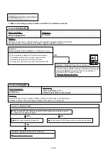
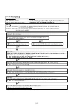
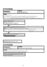
2. When connecting a single split type indoor unit to a network convertor
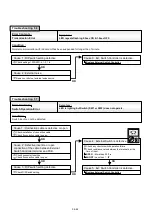
Error Contents :
PCB Error 1
Symptom :
Error Code display [ C 1 ]
All the control items do not operate.
Details :
Condition of occurrence : Synchronization of Network Device was not normally done.
Release condition : When the synchronization of the device is normally done.
Cause 1 : External noise
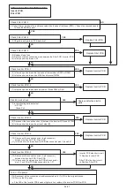
After pressing SW104 of Network Convertor PCB for 5 seconds or turning on power.
Does error code display reappear?
Cause 2 : Network Convertor is defective.
Replace Network Convertor.
It is not a defect of PCB. Remove the surrounding noise source.
Remove the surrounding noise source.
YES
OK
NO
Trouble shooting 70
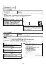
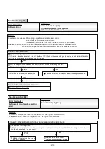
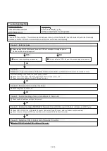
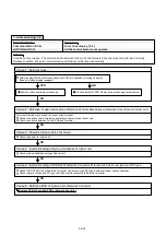
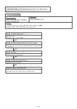
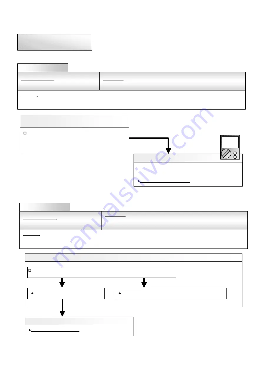
Error Contents :
Power Supply Error
Symptom :
No display
Details :
Condition of occurrence : Normal power is not supplied. 7 segment indicator is defective.
Release condition : Normal power is supplied. 7 segment indicator is normal.
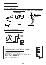
Cause 1 :
Power supply cable installation is defective or open.
Check following installation and reset the power supply.
(1) Installation of power cable on power supply terminal.
(2) Connection between Power PCB and Terminal.
(3) Connector condition between power PCB and Main PCB.
Cause 2 : Network Convertor is defective.
If normal voltage (220V) is applied to power supply
terminal of Network Convertor, there is a possibility of
defective PCB. Proceed as follows.
Replace Network Convertor.
OK
Trouble shooting 69
AC
04-71
Содержание Airstage J-II
Страница 1: ...Small VRF system for light commercial and home use SERVICE MANUAL ...
Страница 2: ......
Страница 6: ......
Страница 7: ...1 TEST RUN ...
Страница 8: ......
Страница 27: ...2 OUTDOOR UNIT OPERATION CONTROL ...
Страница 28: ......
Страница 42: ......
Страница 43: ...3 INDOOR UNIT OPERATION ...
Страница 44: ......
Страница 63: ...4 TROUBLE SHOOTING ...
Страница 73: ......
Страница 170: ......
Страница 171: ...5 APPENDING DATA UNIT ...
Страница 172: ......
Страница 174: ...MODELS AUXB07 AUXB09 AUXB12 AUXB14 AUXB18 AUXB24 05 02 5 2 WIRING DIAGRAM 5 2 1 Indoor Unit ...
Страница 175: ...MODELS AUXD18 AUXD24 AUXA30 AUXA36 AUXA45 AUXA54 05 03 ...
Страница 176: ...MODELS ARXB07 ARXB09 ARXB12 ARXB14 ARXB18 05 04 ...
Страница 177: ...MODEL ARXB24 MODELS ARXB30 ARXB36 05 05 ...
Страница 178: ...MODEL ARXB45 05 06 ...
Страница 179: ...MODEL ARXA24 MODELS ARXA30 ARXA36 ARXA45 05 07 ...
Страница 180: ...MODELS ARXC36 ARXC45 ARXC60 MODELS ARXC72 ARXC90 05 08 ...
Страница 181: ...MODELS ARXD07 ARXD09 ARXD12 ARXD14 ARXD18 ARXD24 05 09 ...
Страница 182: ...MODELS AB A12 AB A14 AB A18 AB A24 05 10 ...
Страница 183: ...MODELS AB A12LBTH AB A14LBTH 05 11 AB A18LBTH AB A24LBTH ...
Страница 184: ...05 12 MODELS AB A30 AB A36 AB A45 AB A54 ...
Страница 185: ...05 13 MODELS AB A30LBTH AB A36LBTH AB A45LBTH AB A54LBTH ...
Страница 186: ...MODELS AS A07 AS A09 AS A12 AS A14 05 14 ...
Страница 187: ...MODELS AS E07 AS E09 AS E12 AS E14 05 15 ...
Страница 188: ...MODELS AS A18 AS A24 AS A30 05 16 ...
Страница 189: ...05 17 MODELS AS A18LACH AS A24LACH AS A30LACH ...
Страница 190: ...05 18 MODELS AJ A36 45 54LALH 5 2 2 Outdoor Unit ...
Страница 195: ...6 DISASSEMBLY PROCESS ...
Страница 196: ......


